Thursday, May 15, 2014

Back to Life

It's been a while since I was able to spend some time in the workshop, but today I managed to set aside an hour or so to look at the Bush SUG91 chassis again.

After a bit of coaxing, it's now sitting on the bench playing Smooth Radio on 1332kHz. The wave change switch is very intermittent though, even after a good dosing with Servisol.  


The only slightly worrying thing is a significant frequency drift. In the last 20 minutes or so I've had to re-tune it slightly several times. I suppose that this might be due to the dodgy switch, (or perhaps because because I gave the oscillator section a good soaking with switch cleaner!)  I'll see what happens if I leave it on test for a while. 

At least I'm one further step towards finishing this one. The restored cabinet has become a permanent fixture in the kitchen, but fortunately my wife likes it.

Keep listening!

Monday, May 05, 2014

Another project

 I did say that I wouldn't buy any more radios, at least until I had finished ( and possibly sold) the current projects.

However, following a trip to a Bank Holiday car boot sale, I now have a GEC BC5645  from around 1956 to add to the 'to do' list!


At £10 it was a pretty good deal; it looks like it's complete, and without any damage to the bakelite or plastic. It's also got VHF FM, which none of my other vintage radios have.

Keep listening!

Friday, April 18, 2014

The sound of silence

Well the replacement CL33 valve arrived safely via Royal Mail (even though the package wasn't marked as fragile) and earlier today I had another go at powering up the SUG91 chassis.

The valve heaters glowed once again, and the HT came up to around 245V on the rectifier cathode. Everything began to look good, but the loudspeaker remained suspiciously silent. After a couple of quick checks with the AVO it became obvious that the primary of the output transformer was open circuit!

I thought that I had checked that earlier in the restoration... but perhaps not.

I'm a bit suspicious that both of the faults have been around the output stage. Perhaps the valve suffered a catastrophic failure (excess grid current caused by a leaky capacitor perhaps) and took out the transformer?

So now I'm looking for a replacement, and the radio will have to stay unfinished for a while longer.

Keep listening!

Sunday, April 13, 2014

Not quite as I hoped...

I had hoped to get the Bush SUG91 completed this weekend, but unfortunately I found a fault that had not been picked up during the restoration.

On powering it up for the first time (via an isolating transformer, because in this set mains neutral is connected to chassis) I was greeted by a nice bright pilot lamp, but no glowing valve heaters. All the valve heaters are wired in series, and as expected one was open circuit;  unfortunately it was the  CL33 output pentode, which I don't have in stock.

I managed to get one from the usual internet auction site, so hopefully in a few days I will be able to get it working.

I did manage to finish the cabinet though, and I'm very pleased with how it looks.


I've deliberately left a few blemishes and imperfections, as I wanted it to look used but cared for, rather than brand new.  I was thinking of selling this one when it was finished, but now I like it so much that I might keep it.

Details of the electronic restoration will follow, so come back later if you want to know what it took to get this one working again.

Keep listening!

Friday, April 11, 2014

Fixing Woodworm Holes

I mentioned in an earlier post that my Bush SUG91 cabinet had suffered from woodworm sometime in its history.

During restoration of the cabinet I realised that if I filled the holes with wood filler, the filler would be a different colour than the surrounding wood after I had applied wood stain.  I believe that some types of filler will take a stain, but not any of the ones that I had in my workshop.

My wife came up with a brilliant idea; dip a cocktail stick into PVA glue, she said, and poke the stick into the wormhole. Once the glue dries, cut off  the stick close to the surface of the wood, and sand down whatever remains standing proud.

Brilliant idea! It worked really well, and after applying the stain the repairs are almost invisible.

Keep listening!

Bush SUG91 Cabinet Restoration

The old damaged veneer came off easily. After using a heat gun to gently soften the glue, I was able to peel the damaged veneer off with a craft knife blade. A quick sanding removed all traces of the old glue and left a smooth surface ready to accept the new veneer.

Damaged veneer removed

One large piece was fixed onto the top surface using PVA glue. I then clamped another piece of wood on top to keep the veneer flat whilst the glue dried.  For the two curved surfaces I used contact adhesive, as clamping these in place while PVA dried would have been very difficult. The glue I used allowed a small amount of movement before bonding firmly, and I cut the veneer to shape as closely as I could before applying the glue.


Top and one side complete

I allowed the glue to dry overnight before carefully removing the excess veneer with a very sharp craft knife blade. The rough edges were then sanded down using fine sandpaper on a wooden block.

This was my first attempt at applying veneer, but on reflection it went better than I had expected. The finished result looked pretty good, although I didn't get a perfect clean edge between two joining pieces on the top surface. A lot of sanding was required to get a smooth surface ready for lacquering

.
After staining
The cabinet sides and bottom panel originally had a very dark brown lacquer finish. Unfortunately the new veneer is a different shade than the original, so to reduce the final  number of colours I decided that a new colour scheme was needed. The front and control panel were just sanded and re-lacquered; all other surfaces were treated with dark oak stain before lacquering.

Once the lacquer has hardened I will give it a polish and then start re-assembling.  I'll post more details and photos later.

Keep listening!

Tuesday, April 01, 2014

Another Bush radio

I picked up a Bush SUG91 radio for £10 in December, and its been sitting in my workshop ever since. I believe that this type of floor standing sets were known as 'console' sets. It's a big old beast, but with its 10" speaker and large cabinet I'm hoping it will sound good.

This is the first set in my collection that I have been able to date exactly; a quality control label inside shows that it passed its final test on 27th January 1947.  

The chassis looks very similar to a Bush DAC90, but with the addition of shortwave and a gram input. The SUG91 is an AC only set, but with an auto-transformer instead of a proper double wound transformer. I'm not sure why this was, as the cost saving must have been very small.  (There was also an AC/DC version called the DUG91 which used a dropper resistor)

As with AC/DC sets though, the mains neutral is connected to chassis, so it will need the usual safety precautions taking. There is plenty of space in the cabinet, so I might fit an isolating transformer inside if I can find something suitable.

Bush SUG91 radio

I can't find the photo that I took before starting work, so this is one of a similar set from the internet. The cabinet was in pretty good condition, but there were a few woodworm holes in one side, and an area of damaged veneer on the top left front edge. I don't think there were any live woodworm left, but just to be safe I gave it a good soaking with woodworm killer, wrapped it in a plastic bin liner and left it in the garage for a few days before bringing it into the house.

The chassis came out a few weeks ago. since then it's been cleaned, re-capped and had some wiring replaced. Over the last few days I have stripped down the cabinet, removing the speaker baffle, control panel and the decorative trim round the tuning scale; these all came out easily after removing screws.

Removing the damaged veneer was easier than I expected, but getting the old lacquer or varnish off has been a bit of a problem. I think I'll leave that story for another day.

Keep listening!

Saturday, March 29, 2014

Radio Recycling

As from today the name of this blog has changed to Radio Recycling.

For the last couple of months I've been blogging about my interest in repairing and restoring vintage radios, so an update was required. (The old name dated back to 2006 when I was presenting a 1980's themed radio show and never got changed)

Thanks to a change in my employment status it looks like I might have a bit of spare time over the next couple of weeks, so expect a few other changes here with the old posts being cleared out, and perhaps a new layout as well. The blog address will also change, as soon as I work out how employ my new domain name radiorecycling.co.uk

My current project is a Bush SUG91 console radio, which was built in January 1947. Restoration of the chassis is almost complete, so some project related posts and pictures will also be appearing here soon.

Keep listening!

Monday, March 24, 2014

Wartime Civilian Receiver - Part 5: Finishing touches

With the set working again, the final part of the restoration entailed making replicas of the top panel and rear panel labels, and sticking these onto the cabinet.

Top label in place

The design for the top panel label was available on the web; all I had to do was download the image and print it full size. I did consider using the water-slide transfer paper for this, but I finally decided to use a colour laser printer and ordinary paper.  After sticking it in place I gave the label a couple of coats of spray lacquer to protect it.

Th rear panel label required a bit more effort. Once again a scanned image was available on the internet, but it required a lot of cleaning up with Paintshop to remove odd marks and artifacts. After cleaning up the image I tried to give it an aged look. I wasn't completely happy with the colour though, as on the computer it looked more like somebody had spilled tea on it!

Rear label, cleaned up (click to enlarge)

With the label glued in place and the rear panel re-fitted, the colour doesn't look too bad really.

Rear view, with vintage Bakelite plug fitted

It would have been nice to have repaired the original speaker, or at least fitted a replacement of similar age. For now though I will enjoy it as it is, and perhaps another speaker will turn up at some time in the future.

Since completing the restoration I have determined that my WCR was probably built by Murphy Radio, which means that it would originally have been identified with the code 'U7' somewhere on the rear of the chassis.

Blogging my restoration of this wonderful old set has turned out to be a bigger task than I had originally planned, but I hope that the information in all five parts will have been of interest, and perhaps even useful to anybody who wants get one of these sets working again.

Keep listening!

Tuesday, March 18, 2014

Wartime Civilian Receiver - Part 4: Bringing it back to life

With the chassis work completed, the time had finally come to see if  my WCR would work.

We can bring it back to life!

The restoration had included replacement of all potentially faulty capacitors and wiring, so the possibility of anything going bang when the power was applied was minimal. Some safety checks were still necessary though before power was applied.

I used my Robin 3111 tester to check the continuity between the earth pin of the plug and the chassis, and the isolation between chassis and the mains. This showed a fraction of an Ohm for the earth continuity, and infinite resistance between both sides of the mains and earth (after checking that the set's mains switch was on!)

A multimeter could be used for this, but a proper insulation tester or Megger is preferable as it applies a higher voltage for the insulation test.

Robin Model 3111 tester

A WCR is unlikely to receive anything without an aerial, so I connected a couple of metres of wire to the A1 socket, more than enough to pick up the local AM Gold transmitter around 5 miles away.

I use a lamp limiter when powering unknown sets for the first time. A 100W 240V lamp connected in series with the live supply wire has negligible effect if the radio is working correctly; the current drawn is insufficient to heat the filament and it's resistance is very low. However,  if a fault causes the radio to draw a lot of current the lamp lights, the filament resistance increases and the fault current is safely limited...well that's the theory anyway!


Chassis re-fitted ready for testing

Power was applied, valves began to glow and the lamp limiter didn't...and after 30 seconds or so I could hear noise from the loudspeaker.

It lived!

After removing the lamp limiter I tried again. Tuning around I was pleased to hear three or four stations, but something wasn't right. There was a loud whistle that decreased in frequency as a station was tuned in, dropping to almost zero, but then rising in frequency again as I carried on tuning past the station.

If you read my earlier post you might remember that I had been a bit clumsy in removing the BVA246 IF amplifier valve early in the restoration. It turned out that I had broken the earth connection to the red metalised paint on the glass envelope, and in this receiver this can cause IF instability.

Original BVA246 (EF39) with damaged screening

Fitting a good EF39 borrowed from another radio confirmed that this was indeed happening, and a New Old Stock CV1053 (a military equivalent) was duly bought and installed.

It was great to hear the set working again!

All that remained now was to sort out the rear panel and cabinet labels, and take some pictures of the finished radio. I'll put this all in the final part, coming soon.

Keep Listening!

Monday, March 17, 2014

AVO Test Bridge

Its been a busy week so I've not had much time to spend in my workshop, but I did find enough time to finish off my latest project, an addition to my test equipment collection.

Whilst browsing my favourite internet auction site recently I came across this, an AVO Test Bridge.

AVO Test Bridge

I'd never seen one of these before, but a quick search on the web turned up enough info to get me interested. What better than vintage test equipment to test vintage radios?  It looked too good a deal to miss out on!

The ATB is the same size and  shape as an AVO 7, but it will test resistance, capacitance and capacitor leakage. It's basically a Wheatstone bridge, with a sensitive valve voltmeter driving a balance meter. With the desired range selected, the dial is rotated until the meter reads a minimum value; the component value is then determined by multiplying the reference for the selected range (100pF/10nF/1uF or 100R/10K/1M) by the number on the dial. An additional setting also allows an external reference resistor or capacitor to be used instead of an internal reference. The leakage tests applies a high voltage to the capacitor via a neon lamp, which flashes repeatedly if there is any leakage current.

All it needed was a new electrolytic capacitor and a couple of polyesters to replace the old wax paper types. It's simple to use, and it appears to be surprisingly accurate for something that is nearly 70 years old. (The last four digits of the serial number visible on the meter scale are 1144, indicating that it was made in November 1944)

The total cost of bits including a bit of vintage type three core mains cable came to under £5, and with a total outlay just over £30 I reckon that I got a bargain.

I went back to the seller a few days later and bought another bit of kit, an AVO allwave oscillator. I'll leave that story until another day.

Keep listening!

Wednesday, March 12, 2014

Wartime Civilian Receiver - Part 3: Electronics and Tuning Scale

Before setting to work on the chassis I decided to remove the valves and put them somewhere safe. The pins on their Octal bases needed some persuasion to part from the sockets, and I made the mistake of grabbing the one of the valves by the glass envelope. I didn't pull it hard at all, but I heard a slight cracking noise from the joint between the glass and the base. It didn't look too bad, but it turned out to be a problem later.

I started by replacing all the wax paper capacitors, re-stuffing their cases with new polypropylene film types. This was the first time I had done this, but I found that once the old capacitor had been gently heated in a vice with a hot air gun, the insides could be pulled out easily with a pair of pliers to leave a hollow tube. With the new capacitors fitted snugly inside I used the recovered wax to seal the ends of the tubes. I used a similar method to re-stuff the cathode bypass electrolytic capacitor for the audio output valve.


Chassis after capacitor replacement

The WCR originally had three 8uF smoothing capacitors. With everything else looking original I was reluctant to use modern looking capacitors, but I did have some fairly chunky 10uF 500V electrolytics that looked like they might have a good ripple current rating. So, after re-forming them I set about making them look old.

Disguised electrolytics

I tried several methods before settling on brown paper parcel tape, wrapped around to make a cardboard cylinder with the capacitor inside. Circles of cardboard with a hole punched in the middle then slipped over the leads, sealing the ends of the tube. These discs were coloured red or black using a Sharpie pen. I used brown paper to make labels, copying the design from an old TCC capacitor as best as I could using Microsoft Publisher.  I then stuck the labels on and dipped the whole capacitor in melted candle wax

The capacitor securing bracket had long gone, so after studying a few WCR photos on the web I made a 'V' shaped bracket from thin aluminium and secured it to the chassis using two existing 4BA screws under the transformer.

Its worth noting that the negative of the reservoir capacitor goes to the centre tap of the HT secondary winding, and not to chassis like the other two smoothers.

i
Another under chassis view - note coil top left

The wires from the chassis to the output transformer were replaced with some original looking wire that I bought from www.savoy-hill.co.uk. This 9/0.2 stranded wire has a cloth covering bonded over the top of the plastic insulation.

The mains power lead had been been cut off (it wasn't original anyway) so I fitted a very authentic looking modern 3 core cable. The mains switch turned out to be intermittent and had to be replaced.  The earth wire was securely bonded to the chassis, and a new length of silicone wire was run from the live side of the switch to the voltage tapping on top of the transformer. A 1A fuse in the plug completed the job.

Whilst checking the wiring I found that a wire had become detached from the coil mounted on the chassis. It looked like I might have broken this when trying to straighten up the tag board. Another lesson learned!


New tuning scale transfer

The paint on the tuning scale and the disc was badly blistered, so after making a scan of the scale I removed the paint with Nitromors. I sprayed the metal with a coat of etching primer, followed by a couple of coats of cream coloured cellulose. The new scale was then created by making a close copy of the scanned image with Visio and printing it onto water slide transfer paper. After a few unsuccessful attempts in applying the transfer I managed to get the result above.

The set was then ready for testing. I'll be blogging more about this later.

Keep listening!

Thursday, March 06, 2014

DON'T just plug it in!

Several vintage radios in my collection came from my favourite online auction site, and I regularly browse there to see what is currently available. Unfortunately the radios that come up for auction often have silly starting figures, or ludicrous buy it now prices, or are described as 'rare' or even 'very rare' when they are not.

I also regularly see sellers describing how they found a radio and plugged it in to see if it worked. I wish more people understood the risks in doing this, because I'm sure that they wouldn't be so keen if they knew what could happen. I've also cringed at seeing pictures of sets with obviously dodgy wiring, live chassis sets with the back covers missing, and even dangerous modifications done by previous owners!

If you are bold (or daft) enough to plug an unknown radio set into the AC mains, then your efforts are quite likely to be rewarded with a loud bang and/or the smell of burning. If you are lucky it might appear that nothing nasty happens, but there is a good chance that you are still damaging the radio and therefore reducing its value.

Until the early 1950s radios commonly used rubber insulated wiring. The problems is  that after all these years, the  rubber is likely to have perished and fallen off, leaving bare wires to short out on the chassis or other components. This wiring needs to be replaced, or at least checked, before power is applied.

Some types of capacitor will usually need replacing as well, particularly the large 'smoothing' capacitors which usually have sealed aluminium cans. If full power is applied suddenly after years of non-use these can overheat, leak chemicals or even burst. This is really bad news as it can be quite violent, in fact one account I read described the bang it produced as being 'like a gun had been fired in the workshop'.

As a potential buyer you should also be aware that any radio that has been 'tested' in this manner by the seller may be more difficult and expensive to get working than you expect.

A very common example of how damage can occur involved is the grid coupling capacitor on the audio output stage, which is likely to have gone leaky with age. A replacement capacitor will probably cost no more than 50p, but running the radio without changing it could destroy a valve costing £15 or more to replace. If you are unlucky the failing valve will also destroy the output transformer as well. The solution is then either a replacement from another set, or in the case of a rare set, an expensive re-wind by a specialist. (This is why I usually check the transformers before starting restoration work).

Vintage radios don't meet modern safety standards for electrical appliances and need to be treated with some respect. If you do not then there is a very real risk of serious injury, death or fire. Making old radios safer is an important part of bringing them back to life, and unless you understand how to do this then I suggest that you leave it to others that do.

There are several good vintage radio forums on the internet, and in my experience the experts who use them are always happy to advise people who ask for help, whether they be experienced or complete beginners.

Safety should always come first.

Keep safe!

Sunday, March 02, 2014

Wartime Civilian Receiver - Part 2: Chassis and cabinet repair.

I spotted this WCR in 2013 at a 1940s event held in a local village, where it had sat on the stall all weekend getting little or no interest. I had already done a bit of research and had a pretty good idea of what it was, but I wasn't keen on paying the £40 the seller was asking. Late on Sunday afternoon I went back to the stall expecting it to have been sold, but there it was. The seller was keen to get rid of it and quickly offered it to me for £25. Deal done!

Chassis after the initial cleaning

After carrying it home and inspecting it more closely my initial pleasure in getting a bargain began to reduce somewhat. The radio was obviously complete, but the cabinet looked like it had been kicked down the garden path and the chassis was rusty. Wondering if I had taken on too much this time, I put it on the shelf until I could find enough time to work on it properly.

Several months later the fibre back panel broke into two pieces as I removed it; not really a good start! I stuck the bits back together with UHU glue, and then clamped both pieces to the workbench for a few days while the glue did it stuff. I didn't really expect it to work, but the repair seems to have held.

After carefully removing the valves I found that the chassis rust was less extensive than I had first thought. The top of the chassis was only lightly rusted, and a couple of hours scrubbing with a brass brush removed all but a few stubborn patches. The front and  underside of the chassis were pristine, except for the inside bottom rear edge.

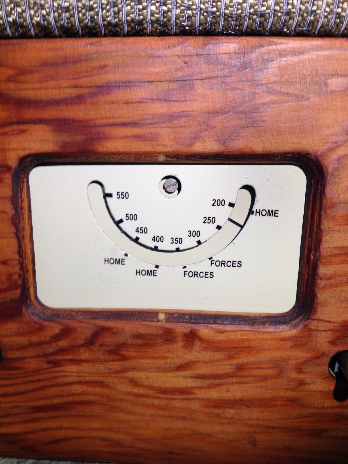
Chassis front view, tuning scale removed.

Once all the loose rust and dirt had been removed I treated the metal with a rust converter liquid, taking care not to get it on the aluminum IF cans. After a few hours all the rusty areas had turned a bluish black colour. There were some rusty patches on the steel parts of the tuning capacitor, but a careful work over with the brass brush removed this as well.

The original dust bag around the speaker had lone gone, and I thought that I could see some damage to the paper cone.  After removing the four wood screws, the baffle and speaker were removed from the cabinet.

Here was the first evidence that the Phantom Bodger had been at work on this set! A horrible yellow material had been used to replace the original speaker fabric, it was far too thick and totally unsuitable for the job. This was quickly removed, revealing a very sorry looking speaker.

Just horrible!

The speaker was removed along with the fixing bolts, which had been overtightened so much that they had almost pulled through the wood. To do this I had to remove the two horizontal wooden mouldings. The oversize holes left by the bolts were plugged with wood filler, and the wooden mouldings glued back into place. The replacement speaker would have to be held in with wood screws.

Original speaker before removal

I initially tried to repair the speaker cone, but after some success in gluing the torn edges together, I discovered that the voice coil was out of alignment and was scraping against the magnet. I learned a lesson here, next time I will check the alignment first.

I couldn't find the manufacturer's code anywhere on the chassis and I assume that it may have been obliterated by the rusting.  The speaker was however clearly labelled Plessey;  was this the first clue to my set's origin?

Plessey 6 inch speaker

May 1944 is clearly visible on the cork gasket of the speaker. Since the WCR went into production in June 1944, this suggests that my set may be one of the early ones.

I cut a piece of Tygan speaker cloth to size and carefully fitted it, taking care to keep it taut while fixing with staples. It took a few attempts before I was happy with my work. Purists might argue that the Tygan isn't right for a WCR, but I had plenty in stock and it does look smart.

Turning to the cabinet, there were a few loose joints that had to be glued together. I used Evostick wood glue for this, poking it into the joint with a cocktail stick before clamping it together and leaving it overnight.

The cabinet is made from soft pine and was covered in dents and abrasions. It  also had some form of varnish applied by a previous user.  I decided to take a fairly robust approach, and attacked the cabinet with fine sandpaper.  After a few minutes I thought I had made a mistake, as the lighter areas of the wood were sanding away too easily, whilst the darker, harder areas remained. This gave a textured finish with patterning somewhat like a tiger's stripes. I decided to press on, but kept the sanding to the minimum required to remove most of the dents and marks.

After sanding I gave the wood a coat of Danish Oil. This went on clear but gave the wood a slightly darker finish when dry. This was left to dry overnight before applying a second and final coat. After a good rub down with a beeswax polish I think it looks pretty good!

The finished cabinet

Later on I'll post details of the electronic restoration, so come back for more if you are interested.

Keep listening!

Saturday, March 01, 2014

Wartime Civilian Receiver - Part 1: Introduction

During the latter half of World War 2, the British government determined that there were a million or more UK households without a working radio.  The manufacturers had stopped producing consumer sets in order to concentrate on war work, so no more new sets were available. Faulty sets often didn't get repaired, as many radio technicians and engineers had been called up for military service.

A family gather around their wireless set during WWII (photo: BBC)

Recognising that the wireless was an important source of information and propaganda, the government created a scheme to produce domestic sets cheaply and in bulk, but using the minimum of materials.  The task of designing this radio was assigned to Dr G.D. Reynolds of Murphy Radio Ltd. The final design was then given to 42 different manufacturers, who were contracted to produce identical looking sets. Whilst this seems strange today, the government were concerned that customers might prefer one manufacturer over another, presumably leading to supply difficulties, and making them anonymous avoided this. Manufacturers were therefore not allowed to put their name or any identifying marks on the finished set, although they were allowed to make small changes to the design in order to use stocks of components that they had. Most of these differences appear to have been things like loudspeakers and transformers, but there were a few minor circuit changes as well.  Each manufacturer was allocated a code (A1 to A42) from which a technician could determine who the the manufacturer was when carrying out warranty repairs.

Wartime Civilian Receiver - AC Version

The cabinets were very basic, made from soft pine wood, with two vertical  pieces of hardwood on the front for decoration.  The tuning was also extremely basic with no reduction drive or glass scale, and instead of the exotic-sounding names found on pre-war sets, the WCR tuning dial has only 'HOME' or 'FORCES' stations. The set was medium wave only , as the long wave broadcast service was closed down during the conflict to prevent German aircraft from using it for navigation. A few sets were produced as MW/LW after the war (using a design produced, I believe, by Bush Radio) and these are now quite rare. Many more were converted by radio shops or by the owners themselves.

The WCR was produced in battery only and AC mains only versions, and went into production in June 1944. It was priced at £12 3s 6d and 175,000 AC versions were sold in the first year.

Electronically the set is a four valve 'short' superhet, but with the traditional detector valve replaced by a 'Westector ' metal oxide rectifier.

Wartime Civilian Receiver - Battery Version

Although some cost savings were obviously made, having restored my AC set I'm not convinced that the WCR was actually as cheap to build as the  'utility' design implied. The mains transformer for one seems to be rather larger than it needs to be, and could have been avoided altogether if a transformerless AC/DC design had been adopted, as was very common in post-war sets. There would have been other advantages in doing this as DC mains was still widely used in the UK during the forties.

Given its simplicity, the WCR seems to work surprisingly well. Mine is working nicely on the workbench as I write, but needs a bit more 'soak' testing before I'll be happy to call it completed. I'll then be taking lots of photos before putting it back together.

Details of the restoration will appear on here soon, so come back if you are interested.

Keep listening!

Tuesday, February 18, 2014

Eddystone EC10 Communications Receiver

Here's my first featured radio, an Eddystone EC10 Communications Receiver from the mid-1960s.
It has five bands covering 550 kHz to 30 MHz. It's quite heavy for a battery radio, but seems to be very well built.

This has just come off my workbench, so before it goes back to its owner I thought I'd put a picture and a few words about the repair on here.


This EC10 belongs to my mate Jonathan, who took it off the shelf where it has sat for a few years and found that  it didn't work anymore. All of the radios that I have worked on recently have been valve (tube) based, so this was a good opportunity to fault find on something with transistors.

I was half expecting that the transistors might be the problem. Many of the devices produced in the 1960's (and possibly later) had tin plated cases which, it is now known, turned out to be a serious design flaw. Tin has some strange properties and over the years crystalline 'whiskers' can grow like stalactites inside the case, eventually shorting out the internals of the transistor. Even so-called new old stock (NOS) transistors can be faulty for this reason, even though they have never been used.  When good tested transistors appear on the auction sites they often sell for silly prices. One seller I found was asking £15 for one OC171 transistor, and there are six of them in this radio!

When I switched this radio on it was obvious that it was pretty 'deaf'. The only thing I could pick up, even with an external aerial, was the local Gold AM station on 1332 kHz and that was extremely weak. I'm less than 5 miles from the local broadcast transmitter so obviously the radio was suffering from very poor sensitivity! It also had a 'rushing' noise from the loudspeaker which didn't change in level when the volume was twiddled. The band change switch was also very noisy when operated.

I decided to change all the old electrolytic capacitors first.  Some repairers like to leave these as original and only change those that prove to be faulty. In my experience many or all of them will prove to be duff, and much time and frustration can be saved by applying what some have called the 'shotgun approach'. At only a few pennies each its cheap enough to change them all in one go.  Many modern capacitors are of a similar size to those used in old transistor sets, and they can be fitted without looking too much out of place.

After changing all the old capacitors I started looking for the source of the noise. A bit of simple fault finding pointed to a noisy 180K resistor in the driver stage. After replacement the noise hadn't gone away completely, but I thought it was reduced to an acceptable level.

Next, I decided to take a can of switch cleaner to the wafer switches. There are six of these, ganged together on the shaft  turned by the Band Change knob.  After giving these a good cleaning I plugged the aerial back in and suddenly loads of signals came pouring in.

A fairly simple repair then, but I'm quite pleased with the result. The receiver seems quite sensitive, and definitely better than my workshop Ekco valve radio. The audio quality is a bit harsh though and I would probably find listening to music on a bit tiresome after a while, but in fairness as a communications receiver this isn't what it was designed for.

Its a real pity that so many of the interesting short wave stations have closed down and there is much less to listen to these days. I reckon owning one of these sets in years gone by would could have been a lot of fun!

The workbench is now free for me to finish my Wartime Civilian Receiver rebuild. More about that coming soon.

Keep listening!

2014: Blogging, Facebook & Vintage Radios.

I can't believe that its been nearly seven years since I last wrote anything here! I blame Facebook, Smartphones, Twitter and all the other things which seem to be spoiling the art of communication.

So why start blogging again now? Previously my blog was a bit of fun, a place for a bit of a rant and a few insights into my life that I chose to share; basically all the stuff I do on Facebook now. However, from today I'm going to start putting what I hope will be worthwhile content into this blog.

About a year ago I started restoring vintage radios, and I occasionally put  photos of them on Facebook.  These were mainly 'before and after' pictures and I was surprised by just how may of my friends took an interest, and even made suggestions on which model of radio I should do next. I've now successfully brought six old and unloved radios back to life, and over the months I've found it to be a very relaxing and satisfying hobby, therapeutic even. Its been difficult at times, and this brings me to my main reason for re-activating this blog.

Although I'm a qualified electronics engineer, much of my knowledge & experience wasn't relevant to 50+ year old  valve (tube) technology. I had learned about this stuff, but that was way back in my basic training over 30 years ago. Undeterred, I found information and help from many sources, including old books from second hand shops, internet forums and several really good websites. I now want to share some of this knowledge and the experience I have gained with others on the web.

I've had some really pleasing results, I've had a few things that haven't gone as well as I had hoped, and I've also made a few mistakes along the way. I've found a few sources of vintage components, loads of useful information and some helpful tips, some learned from others and some learned myself the hard way. I'm hoping that if I start to put some of it on here, it might be helpful to others as well.

Keep listening reading!


Thursday, August 10, 2006

A weekend north of the border

Last weekend was the Truckfest Scotland show in Edinburgh, and as usual I was part of the team of presenters on Truckfest FM, the show's own radio station.

On the whole it was great fun with decent weather for most of the weekend. It was hard work at times, but the evening's made up for it.

You might be wondering how radio presenting can be hard work. Well, it isn't really...but dragging the whole station around the country in a big van, setting it up for each show and then taking it down again a few days later certainly is.

There are five Truckfest shows throughout the year, and each one requires a surprisingly large amount of equipment, including a temporary broadcast aerial and large satellite dish for the news service. The Edinburgh show is probably my favourite, but the travel can be a pain.


Here's most of the Truckfest crew posing with visiting celebrity Ben Richards, from the British TV programmes 'Footballers Wives' and 'Holby City'

From the left: Vinny (me), Jonathan (JC), Ben, John (JB) and Malc


The other member of the team is Mikey...the baby of Truckfest FM. Here he is with Sally Boazman, aka 'Sally Traffic' from BBC Radio 2.

Sally is a great supporter of Truckfest and she always pays us a visit at the station. Mikey seems to be enjoying her company!


Here's Jonathan with a special guest from the BBC TV series 'Eastenders'. He may play gangster and all-round baddie Johnny Allen, but actor Billy Murray is a really a nice bloke.

Wednesday, August 02, 2006

Radio Waves

Recently I heard about another group of people who were opposing the building of a mobile phone tower near to a school. I accept that most people who raise objections like this do it for the best reasons, usually concerns over the health of their children, but unfortunately these concerns are often due to a lack of understanding.

Before I continue, let me say that although I am a qualified radio engineer, I don't work in the mobile phone industry. Don't dismiss what I say as being propaganda, it's not. It can all be substantiated by reading a good radio textbook.

The towers that cause so much concern are called base stations, also known as cell sites. They communicate with your mobile phone using radio signals, providing a link between your phone and the telephone exchanges.

One of the problems is the emotive language used by the media. Instead of referring to radio signals, they often speak about radiation. Whilst this is technically correct, its scares the hell out of people who only associate radiation with atom bombs and nuclear power stations. Radio signals are a form of electromagnetic waves. Although radio waves usually have to be generated artificially, other forms of electromagnetic waves occur naturally.....you know them as HEAT and LIGHT.

Suddenly, radio waves become less scary!

It is a fact that, like light, the further a radio wave travels the weaker it gets. It's called the inverse square law, which means if the distance doubles, the intensity reduces to a quarter.

Sticking with the light analogy, consider a lighthouse. We put a lamp high up a tower, then focus the light into a narrow beam. Why? To make the light travel the greatest distance of course!

We do exactly the same with radio transmitters, but instead of lenses we use aerials.

If you stand at the base of a lighthouse, are you bathed in light? No, of course not! There' s no point in wasting energy illuminating the ground beneath.

The same is true for radio transmitters.

Just for a minute, let's suppose that there might be a risk, however small, from exposure to RF energy from cellphones......

For the reasons I've explained above, a mobile phone user will receive a much higher concentration of radio waves (what engineers call field strength) from the phone held against his head, than he would from being near a base station tower.

Many of these protesters are quite happy to let their little ones have mobile phones. If that's OK, why do they consider the masts to be dangerous?

The fact is, having a base station on a school building is actually a good idea!

All mobile phones reduce their transmitter power as they get nearer to the base station. They do this to reduce the drain on the battery, so you can talk for longer. Having a base station on the roof of a school won't harm anybody nearby, but it would ensure that all the children's phones are operating at the lowest possible transmitter power.

And even though there is still no scientific evidence of risk, there's certainly no harm in reducing our children's exposure.

Monday, July 03, 2006

Radio Ga Ga

I've just had a great weekend in Somerset, doing two shows on an event-based radio station and having a few laughs and beers with the other guys in the team. The van we used to transport the equipment didn't have a CD player, so on the long journey home last night all I had to amuse me was the radio. After tuning round a little, I remembered why I dislike the way radio has gone in this country.

At the risk of biting the hand that (occasionally) feeds me, I have to say that I think the vast majority of UK commercial radio is totally boring and unimaginative.

It's not the presenter' s fault, as all too often they are not allowed to express their personalities or use their creative abilities. Stations run by the bigger radio companies are the worst, those with a 'one size fits all' approach that makes their many radio stations sound almost identical, as I found on my long journey home.

The sad fact is that commercial radio stations exist solely to make money for their shareholders.

Most stations run on extremely tight budgets, but this in itself doesn't make bad radio. The problem is big radio company bosses who dictate minimalist formats because these are the cheapest to implement, and make the most money with the least risk. The result, as I have said, is boring radio.

Any radio professionals reading this would probably point out that these formats that I hate so much are the result of much market research, and are proven to maximise listenership. They would be correct of course..but is it the only way?

I wouldn't want to see the return of the cheesy radio DJs we suffered in the 70s (and I'm not old enough to remember the pirates of the 60s), but instead of bland presenters who only speak every 20 minutes or so, I'd love to see the return of more personality radio. The nearest thing we have to this is BBC Radio 2, (which is probably why it has the UKs fastest growing listener figures) but in my experience few towns are lucky enough to have a local equivalent.