I started by replacing all the wax paper capacitors, re-stuffing their cases with new polypropylene film types. This was the first time I had done this, but I found that once the old capacitor had been gently heated in a vice with a hot air gun, the insides could be pulled out easily with a pair of pliers to leave a hollow tube. With the new capacitors fitted snugly inside I used the recovered wax to seal the ends of the tubes. I used a similar method to re-stuff the cathode bypass electrolytic capacitor for the audio output valve.
 |
| Chassis after capacitor replacement |
The WCR originally had three 8uF smoothing capacitors. With everything else looking original I was reluctant to use modern looking capacitors, but I did have some fairly chunky 10uF 500V electrolytics that looked like they might have a good ripple current rating. So, after re-forming them I set about making them look old.
 |
| Disguised electrolytics |
I tried several methods before settling on brown paper parcel tape, wrapped around to make a cardboard cylinder with the capacitor inside. Circles of cardboard with a hole punched in the middle then slipped over the leads, sealing the ends of the tube. These discs were coloured red or black using a Sharpie pen. I used brown paper to make labels, copying the design from an old TCC capacitor as best as I could using Microsoft Publisher. I then stuck the labels on and dipped the whole capacitor in melted candle wax
The capacitor securing bracket had long gone, so after studying a few WCR photos on the web I made a 'V' shaped bracket from thin aluminium and secured it to the chassis using two existing 4BA screws under the transformer.
Its worth noting that the negative of the reservoir capacitor goes to the centre tap of the HT secondary winding, and not to chassis like the other two smoothers.
 i i |
| Another under chassis view - note coil top left |
The wires from the chassis to the output transformer were replaced with some original looking wire that I bought from www.savoy-hill.co.uk. This 9/0.2 stranded wire has a cloth covering bonded over the top of the plastic insulation.
The mains power lead had been been cut off (it wasn't original anyway) so I fitted a very authentic looking modern 3 core cable. The mains switch turned out to be intermittent and had to be replaced. The earth wire was securely bonded to the chassis, and a new length of silicone wire was run from the live side of the switch to the voltage tapping on top of the transformer. A 1A fuse in the plug completed the job.
Whilst checking the wiring I found that a wire had become detached from the coil mounted on the chassis. It looked like I might have broken this when trying to straighten up the tag board. Another lesson learned!
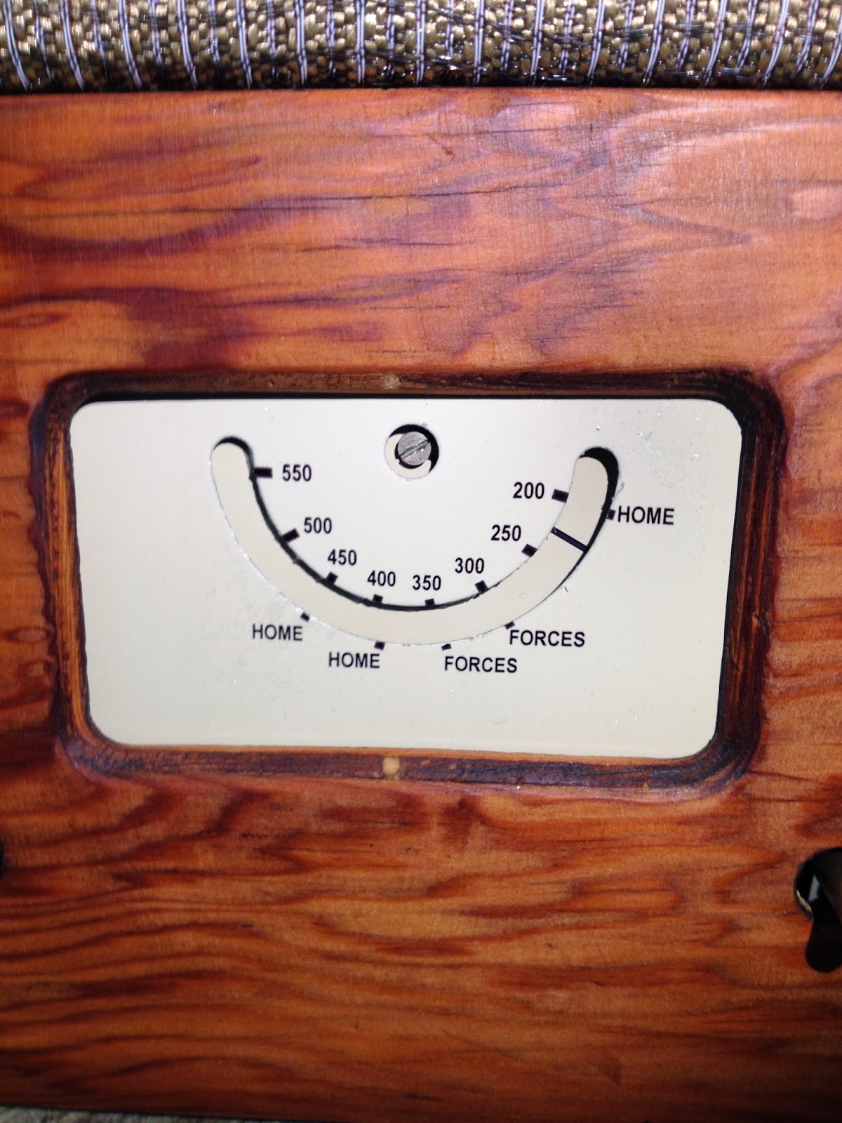 |
| New tuning scale transfer |
The paint on the tuning scale and the disc was badly blistered, so after making a scan of the scale I removed the paint with Nitromors. I sprayed the metal with a coat of etching primer, followed by a couple of coats of cream coloured cellulose. The new scale was then created by making a close copy of the scanned image with Visio and printing it onto water slide transfer paper. After a few unsuccessful attempts in applying the transfer I managed to get the result above.
The set was then ready for testing. I'll be blogging more about this later.
Keep listening!
No comments:
Post a Comment