Wednesday, January 02, 2019

19 Set restoration - Part 2: Initial Radio checks

As I mentioned previously, my 19 Set is a British MKIII one that had that had been rebuilt by REME sometime after WW2, probably in the 1950s.

These rebuilt examples are not to the original spec, having been rebuilt without the VHF 'B' set, but they do have the advantage of having been re-wired with pvc insulated wire. Original WW2 sets may have multiple faults due to crumbing rubber insulation.

My 19 Set as received..note grey colour paint

Everything on the front panel was present and correct, apart from a missing handle on the right hand side. Once the case was off, a quick inspection showed that chassis was complete and as it should be, apart from a high wattage wirewound resistor above the chassis that was obviously not original; I'll come back to this later.

On top of the chassis, adjacent to the PA valve there is a small paxolin board bolted to the chassis with a number of capacitors and resistors on. At this point I hadn't studied the manuals and the purpose of this board was not clear to me, but I did notice that one of the wires (actually the centre conductor of a bit of coax) had broken off one of the tags. It was obvious where it should go, so I soldered it back on. The mica capacitor in the photo looks like it is broken, but is actually OK.

'Broken' capacitor and detatched wire.
The 19 Set has a large number of decoupling capacitors, mostly 100nF. These appeared to be military quality (metalised foil possibly)  types.  With the older type wax paper capacitors my usual approach is to replace all on sight, but the number of capacitors in the 19 Set would have made this a very big job. Instead I just removed three of four for testing on my AVO component bridge. All were very close to their intended value with no leakage indicated, so I just popped them back in. There is a slight risk in doing this, and I may yet have to replace some if they prove to be leaky later on

I did however replace the one on the audio amplifier grid (usually referred to by restorers as 'that capacitor') and those decoupling the AGC line as these are areas where even a small amount of leakage could seriously upset things.  I also replaced all of the small number of electrolytic capacitors, which fortunately were easy to get at... which most things in a 19 set are not!

Checking resistors is easy and in most cases can be done in circuit. Some of the higher value ones had gone up in value, but most were still in tolerance. I did end up changing a few, like the 470K visible in the photo below. The green screw head is the adjusting slug of the BFO coil, which I'll come back to later.

Replaced capacitor and resistor
So far, so good; everything looked ready for a power up test.

Wednesday, December 26, 2018

19 Set restoration - Part 1: Power Supply


Having won my British WS19 MKIII on an internet auction site I was able to collect it person and check that it was as good as advertised before handing over my cash. Had this not been possible then I might have been reluctant to bid as high as I did.

However it came without its companion power supply, so having confirmed that the radio was indeed a suitable candidate for restoration, my next task was to find a suitable power supply to go with it.

The power supply that I eventually acquired is the PSU No.2 MKIII, Canadian version, which uses a uses a single dual-output dynamotor to produce +275V HT for receive and +500V for transmit. This differs from the British version which has two separate dynamotors, although both types are are interchangeable.

The Canadian version also has a receive-only 'vibrator' mode which uses a mechanical vibrator and transformer, and this usefully reduces the current drawn from the battery. It is also much quieter, although it is doubtful if this would have mattered much in a tank! In vibrator mode a relay starts up the dynamotor whenever the PTT is operated.

The power unit that I received had been quite badly hacked about and 'modified'. A length of 3-core cable emerged from a hole drilled in the front panel, with the remains of a UK-type mains socket on its end. Apparently this was a common post-war modification and some modified units were re-sold for use as inverters for caravans!


Top view showing relay and large capacitor
Most of the changes were easy to undo, apart for the relay from which several contacts had been removed. As can be seen from the photo, this relay is rather specialised and is possibly unique to the 19 Set, but surprisingly after only a few weeks searching I came across a New Old Stock (NOS) item from an internet seller. It wasn't cheap, but I decided that having a fully working supply was worth the outlay.

A rather special relay
After fitting the new relay, the next job was to replace the electrolytic capacitors. There are two 20uF 450V caps in a chassis mounted can adjacent to the rectifier valve.  I couldn't manage to remove this from the chassis, so I fitted replaceements under the chassis, hidden as best as I could. The large capacitor on top of the chassis was extracted from its cardboard tube. The end disc with the terminals was removed and the remains of the capacitor discarded. The leads of two new capacitors were passed through small holes made in the disc and soldered to the terminals. After adding some packing material to the tube (to prevent it it being crushed when the fixing clamp was tightened) the disc and capacitor assembly was glued back in place.

Re-stuffing the big 32uF capacitor

I replaced all but one of the paper capacitors, using mostly 100nF 600V polyester types. This was quite time consuming, as access to some of them was very difficult (and to one impossible!) Having struggled for a while I did manage to remove the front panel for better access, but all my attempts to further dismantle the unit failed. For this reason I was also unable to re-grease the dyno bearings, so instead I setted for running a few drops of oil into each one.


Side view - not much to see!

The cold cathode OZ4A rectifier valve was missing. I could have fitted slicon diodes in it place, but I was able to find a NOS replacement from an internet auction site quite cheaply.

The mechanical vibrator was also missing, so instead I installed one of the excellent solid state replacements available from http://www.royalsignals.org.uk/vibs/. I bought a ready built plug-in replacement for the original vibrator, but they do have part assembled options if you want to hide one in an original casing.

Finally the fuses were checked and replaced with the correct values.

The unit isn't completely silent in 'vibrator' mode as you can still hear a buzz from the transformer laminations, but the improvement in reliability and efficiency is well worth the cost of the solid state upgrade.

The job had taken quite a bit more time and money to restore than I had expected, but I think the result was worth it.

The next task was to obtain the so-called 'dog bone' cable that connects the power supply to the radio.

Wireless Set No.19


Keeping the blog updated during the summer months has always been difficult for me, and this year has been even more busy than usual.  I thought I'd take advantage of a bit of spare time over Christmas to bring the blog up to date

Just before Easter I started  work on my Wireless Set 19, which turned out to be my biggest project in several years.

WS19 in Sherman tank 1943 (National Army Museum Copyright)

The Wireless Set No 19 was designed originally for tanks and armoured fighting vehicles used by British and Canadian forces in WW2, but later also used extensively in jeeps, trucks and even as a man-portable ground station. There are many excellent sources of  information on the internet so I won't go into great detail here, but the WS19 provided two radios in one box, plus intercom facilities for the tank crew.  The 'A' set was for HF W/T or R/T over longer distances while the 'B' set was used for very short range VHF comms between tanks.

My first experience of the iconic '19 Set' was as a kid in the 1970s. Thousands of sets had been sold as army surplus in the 1960s and although I never owned one myself back then, many radio amateurs that I knew did. 19 sets were often heavily 'modified'  or even broken up for spares without too much thought, as they were cheap and pentiful. 40-odd years later 19 sets and accessories have now become very collectable and sell for big money on internet auction sites. I recently saw a complete (but not guaranteed working) WS19 station with an asking price of nearly £1000!

Sometime after the war, large numbers of 19 sets were completely rebuilt (without the 'B' set) and many were then put into storage. Markings on the front panel of my British WS19 MKIII suggest that it was rebuilt at the Newark workshops of the Royal Electrical & Mechanical Engineers (REME). Unfortunately the date has been rubbed off, but based on similar sets I've seen I expect that it would have been late 1950s.


My WS19 MKIII

In the next blog I'll describe what I had to do to get the set working again.

Keep listening!

Saturday, March 03, 2018

A troublesome trio

If you read my previous entry you may remember that I was debating whether to put my R1155 or my WS19 at the front of the restoration queue. I had almost decided to concentrate on the WS19, as it appeared require less work to return to working condition, but then three unexpected and more urgent jobs arrived... all of them HF transceivers!

Clansman RT320,  PSU module removed


 My Clansman RT-320 developed a (nasty) power supply fault


Yaesu FT-757GX

                              My Yaesu FT-757GX had frequency stability problems

Alinco DX-70TH


And finally my Alinco DX-70TH failed
with a duff PA driver transistor!


I was able to start investigating the WS19 power supply while waiting for the Alinco's transistors to arrive. By late in February with all three troublesome radios working again, I was finally able to clear the bench and turn my attention back to restoration work.

More details will follow soon.

Keep listening!


Monday, January 01, 2018

Happy New Year 2018

I can hardly believe that my last blog post was in February 2017, almost a year and two months ago!

I've been meaning to post more radio repair and restoration activities on here, but as often happens, life gets in the way.  It became obvious quite early in 2017 that I wasn't going to get many projects done before the summer's busy period, and this was pretty much how the year continued right up to Christmas.

This time last year I was looking forward to getting my WW2 R1155 receiver sorted. At first all seemed to be going well, with just a bit of re-wiring needed, a few capacitor replacements and some new connectors, all of which I had managed to source.

Unfortunately as I began to dig deeper into it I found some burnt components and wiring that had gone unnoticed in my initial investigation, a discovery that effectively turned a relatively straightforward task into a very much bigger one. By early March an increasing shortage of spare time forced me to abandon the job and put the set back on the shelf for another year.

It wasn't all doom and gloom though. In September, some friends and I were invited to run an Amateur Radio station at a 1940s event held at an Airfield Museum. We didn't really know what to expect from the event and had very little time to prepare, but we did manage to make a few contacts  across Europe on 40 Metres using my 1943 HRO-MX as the receiver. We've been invited back again for 2018, this time with a better location and plenty of time to put together a better range of equipment.

'Y'Service re-enactment with HRO-MX

In the autumn I managed to get my hands on a Wireless Set No. 19, an HF transmitter/receiver that was used extensively in British Armoured vehicles and Jeeps during WW2.  I've wanted one of these for years but they are getting quite scarce now, and even very poor condition sets change hands for silly money. It does look like I've been lucky to get a good one for a sensible price, but I'll save the details for a future blog entry.

I've yet to make up my mind whether to do the R1155 or the WS19 first. Either way, January in the Radio Recycling workshop is going to be interesting.

Keep listening!

Saturday, February 25, 2017

R1155 progress

Restoration of the R1155L is not progressing well at the moment, digging into some of the more inaccessible areas has uncovered a number of burnt resistors and wiring around the bias board. Most of the burnt bits appear to be part of a modification done by a previous owner, who in future I'm going to refer to as Bill the Bodger (a British term for a person who makes or repairs something badly or clumsily). His shoddy efforts have really created a lot of additional work for me.

It looks like Bill has attempted to re-wire the Meter Amplitude potentiometer into the bias circuit, although without a lot of effort I'm not going to find out why. I'm guessing that it might have been intended for variable RF Gain, but whatever it is it will have to come out.

On a more encouraging note, I was delighted to find that the two VI103 'magic eye' indicators I bought last month are both usable. The R1155 uses one as a tuning indicator, driven by the AGC voltage. Unfortunately the phosphor that gives the green glow seems to fail very quickly, resulting in a very dim display even though the valve emission is still good. Finding serviceable originals is now very difficult; New Old Stock (NOS) near-equivalents are available, but these are getting expensive.

VI103 'Magic Eye' on test, control grid grounded.

The seller said they tested OK on his AVO valve tester, but he didn't give any indication of how bright they were. They probably aren't as bright as they should be, but they are usable and at the price I paid I'm definitely well pleased with them. The seller was in Eastern Europe, so it might have been interesting to find out how two British Air Ministry valves got there.


From Eastern Europe via eBay!

The original VI103 in my set had been replaced with an EM34, a similar civilian indicator with a slightly different 'eye' shape. Fortunately I have now discovered that the pin out of the two types are slightly different, so the wiring of the socket must be changed back before I re-install a VI103!


Wednesday, February 15, 2017

Stuffing!

Old wax paper capacitors are notorious for going leaky. Even if they are not significantly leaky now, you can guarantee that they will be at some time in the future. My approach is usually to change all such capacitors on sight, and this receiver will be no exception to this rule.

Unusually, in the R1155, the decoupling capacitors are all housed in aluminium cans bolted to the chassis. Most of these have three 100nF capacitors inside, others have only one. I want to preserve the original appearance of the chassis, so I will be removing the contents of these cans and replacing them with modern components.

One of several capacitor cans

Removing a can from the chassis is easy. You just cut the existing wires close to where they enter the can, leaving the wires connected so you can see where you have to connect the new wires. Undoing the nut and pulling the can from the chassis completes the easy part of the task!

At this point you have a choice in the method for opening the can. Some people use a pipe cutter to separate the cylindrical part into two pieces, and then glue it back together afterwards using epoxy. Foil tape can be used to hide the join. Others may use a hacksaw to remove the end of the can, and glue that back in place afterwards. 

Fortunately I discovered an easier and neater way to do it.

Once the capacitor can has been removed, put the nut loosely back onto the threaded part. Clamp the nut in the jaws of a small bench vice with the capacitor standing vertically upwards. Now grab the end of the can and carefully rock it back and forwards, and side to side.  The cylindrical part of the can is crimped on to the threaded base part, and this rocking motion will loosen the crimping.  The trick is not to be too rough and tear the metal! Carry on this gentle loosening process until you can pull the can vertically upwards and separate it from the threaded part, which stays in the vice.

Removing the original capacitors from the can. Messy!
Carefully dig out the black pitch from the open end of the can with a small screwdriver. The now exposed capacitors inside need a bit of persuasion to come out of the can.  I use a large wood screw to do this; just screw it into the waxy yellow mass inside the can and pull it out.

In the next blog entry I'll tell you how I re-stuffed this can with new capacitors and re-assembled it.

Keep listening!

Saturday, January 21, 2017

A little distraction

I've not made any progress with the R1155L since it appeared on my workbench earlier this month. It's still there, it just got pushed to one side. I've not been idle though, over the last couple of weeks I've been building the power supply and audio amplifier that I will eventually be needed to run the receiver. I could have built one with modern components, but I decided that a valve (tube) design would be more appropriate.

Front view. The hole is for a neon 'HT on' indicator.

The power supply is built onto a simple folded aluminium chassis purchased from a seller on eBay, and in the best tradition of radio recycling, most of the parts are recovered from other radios and electronic equipment. After the chassis the most expensive item was the 5Z4G rectifier valve, although the KT63 tetrode could have been quite costly if I didn't have one already.

Rear view of KT63 (left) and 5Z4G (right)

The transformer was the most difficult item to source. With multiple windings to provide HT, rectifier heater and LT supplies, this style of transformer probably hasn't been manufactured since the 1960s when silicon diodes began to replace valve rectifiers. An R1155 (especially one with the DF valves refitted) will require more heater current than most domestic radio transformers could provide, so I had to limit my search to old industrial and military equipment. Fortunately last year's visit to the National Vintage Communications Fair in Warwick proved to be very worthwhile, and I came home with both a suitable transformer and a choke to go with it.

Underside view. All wire is silicone insulated, except for AC cable.


The connection to the power supply are brought out to a tagstrip on the rear of the chassis. HT- and chassis are on separate terminals, and the LT supply is also isolated from the chassis. This will allow me to add wire links as required for use with either my R1155 (floating HT & grounded LT) or my HRO receiver (grounded HT & floating LT).

The PSU is now working, but for safety's sake it needs to be finished with some form of case. There are dangerous voltages on the transformer terminals just behind the rectifier valve, and also below the chassis.

Building it has been an enjoyable distraction, and its actually the first bit of valve equipment that I have ever built from scratch. Now I need to face the more difficult task...the R1155 itself.

Keep listening!


Friday, January 06, 2017

R1155L first observations

I've had my R1155L receiver for around 3 months now, but today was my first opportunity to get it on the bench for a proper inspection.

I always knew that restoring an R1155 would be a challenge. Even though I knew just how tightly everything is packed into the chassis, with very poor access, actually seeing it close up was a bit of a worry! The R1155 was never designed with maintenance in mind; but with the average wartime life of a Bomber Command aircraft measured in weeks, why would it have been?

As was immediately apparent when I purchased the set, some fool has cut off the pins of the Jones plugs and soldered to the stumps left behind. For God's sake, why would anybody do such a horrendous bodge? If a suitable socket could not be found, then surely soldering to the intact pins would have been sufficient?  I now have the difficult task of replacing these plugs, and it looks like getting access to the screws that hold them in place is going to be a really big problem.

The bloke who bodged the connectors?
I had also noted that VR102 (V9) and both of the VR99As (V1 & V2) are missing. These are part of the DF circuit, and were often removed by Hams to reduce the heater current required by the set. As part of a loudspeaker amplifier modification, V1 had been replaced with a KT63 Beam Tetrode. I had already removed an output transformer which had been added above the chassis, as well as a dreadful 'birds nest' of  capacitors and resistors that had been added under the chassis. These have now been removed, along with any wiring that obviously wasn't original.

DF Section (V1 & V2). Yellow arrows indicate cut wires.
An initial poke around revealed a few more things. It also gave me the opportunity to take some 'before' photographs, which I often forget to do.

The VI103 'Magic Eye' tuning indicator has been replaced by a later civilian type EM34. This isn't totally unexpected. The phosphor on these devices has a short life, and they are often found to be glowing only very dimly, even though the cathode emission is still good.  Unfortunately as the EM34 is a smaller valve, the metal tube it mounts in has had to be made shorter.

Modified Magic Eye
The wiring to both the Meter Amplitude and Meter Balance potentiometers has been modified. The reason for this is not immediately obvious, so I'll have to compare the wiring with the circuit diagram and work it out.

Meter Amplitude & Meter Balance pots. Arrows indicate cut wires
There is a bit of blackening under the chassis below the volume control. It could be soot from a burned up resistor, although the culprit couldn't be seen. Another resistor has been added here. I know access is difficult, but it could have been done a bit more neatly.

Something has been getting hot. Note added resistors; quality job what!
As well as the valves, the set is also missing two tubular aluminum cased capacitors from the DF stage. The bases for V1 & V4 are also missing the aluminium collar onto which the screening can fits. I have spare screening cans, but not the valve base collars, so these have been added to the shopping list.

Holes for the missing capacitors, and a valve socket without the screening collar.
This valve socket should have a collar like the one in the photo above.
On the good side, my initial observation that the set was free of perishable rubber insulated wiring has proved to be 100% correct, so there should not be any need for a re-wire. In fact it appears to be PVC, so I need to be careful not to melt it accidentally with the soldering iron.

Restoring this one is going to be a long job. I also have to  make a power supply for it. More blogs will follow as (hopefully) I make some progress.

Keep listening!


Wednesday, December 28, 2016

Workshop closed for Christmas

December is almost over and I'm keen to make a start on restoring the R1155L receiver, but family duties have to come first and I'll have to wait a few days more until I get home.

Over the last few weeks I've been finishing off other small projects to make space in the workshop, and collecting bits that I will need for the 1155. I've managed to find a couple of 8 pole Jones plugs to replace those hacked by a previous owner, although the mating free sockets are proving more difficult to find.

An original Air Ministry wooden box of valves was a worthwhile addition to the spares collection. I did think that I might have paid too much in the online auction, until I realised that it included a rare VR102. This is one of three valves forming the DF circuit, which many Ham Radio users removed to reduce the heater current.  As I'm intending to restore the receiver into its original configuration, finding a (hopefully serviceable!) VR102 was a big step towards this.

I'll also have to build a power supply. Eventually this will include an audio amplifier, but this can wait until the receiver is finished. Until then I'll make do with a simple version assembled from bits I already have, I just need to find a full wave rectifier valve with a 5V heater.

Tuesday, September 27, 2016

More stuff coming soon.

As usual I was too busy to do much radio restoration work in the summer, but now that autumn is here I'm starting to think about getting back into the workshop.

In the six months since my last blog entry I've acquired several radios. Recent additions to the collection include a Marconi from 1935 and a Philips from 1939, both originally battery models that have been converted to AC. Neither have been into my workshop yet, but they appear to be complete. I also added a Bush TR82B (circa 1960) battery portable which just needed a good clean, and also a Bush VT103 from around 1964, which is working but needs some more attention to improve VHF performance.

I'm looking forward to getting all of these sorted, but this year's first winter project is going to be a big one that takes priority.

R1155L Receiver as purchased
After wanting one for many years, I have finally bought an R1155, the iconic receiver that was used in many RAF heavy bombers (most famously the Lancaster) in World War two.

R1155 Receiver & T1154 Transmitter in an Avro Lancaster
At the moment I'm collecting information and some of the bits that I know I will need, and it will be a month or so before I actually start working on the set. I'll be blogging more about this historic radio over the next few weeks, so if you are interested please come back soon.

Keep listening!

Thursday, March 10, 2016

A 1940s radio with a difference

A few months ago I acquired two Wartime Civilian Receivers, one incomplete and one in a very poor state.

The incomplete radio had no speaker, no speaker baffle, and no valves. The mains transformer also looked like it had overheated, possibly due to a shorted turn, as there was a large pool of melted wax on the chassis under the transformer.  The chassis was beyond repair, but the remains of the case were worth keeping.


I already have a fully restored one of these in my collection (see blogs from March 2014) so initially I was just going put these into storage. A few days later a family member asked me if I could make him a modern radio an old cabinet, which gave me an idea.

The first part of the project was to sand the cabinet to remove the worst scratches and gouges. After repairing  the damaged areas with filler and sanding again I gave the cabinet a few coats of Danish oil. A new speaker baffle made from MDF and covered with speaker cloth finished off the job.

Turning to the chassis, I stripped off all the components with the exception of the tuning capacitor, and put them in my spares box.


The tuning scale and disc were both in poor condition, so after sanding off the remains of the old paint I treated them both to a fresh coat of pale yellow enamel spray paint, as close to the original as In could get. Fortunately I had a some waterslide transfers left over from the earlier WCR restoration, so after the paint had hardened I was able to replace the tuning scale with a pristine new version.

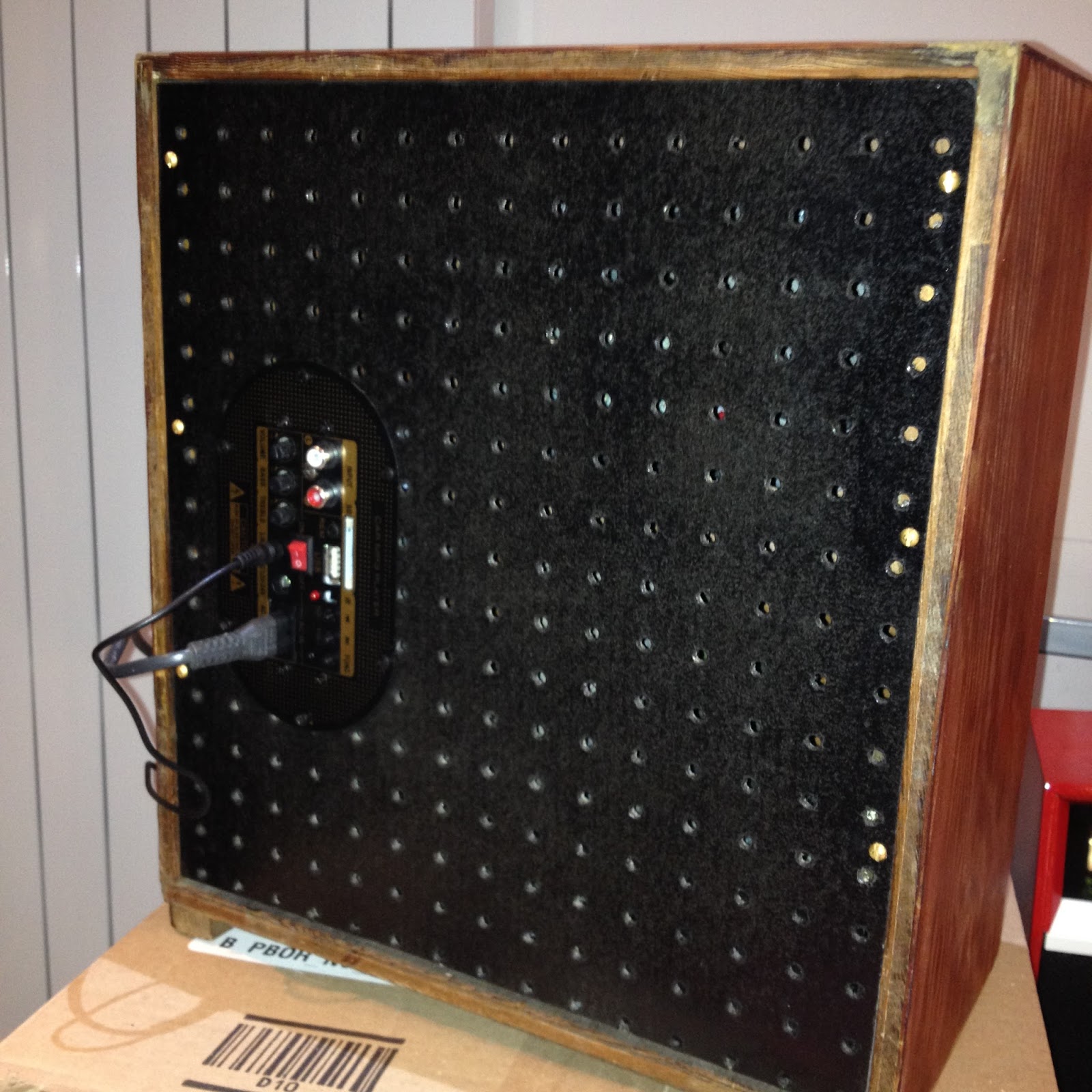
The original back panel was missing, so I made a new one from perforated hardboard; I think its called peg board. I made this the same size as the cabinet, to hide the modern bits I planned to add next.

I fitted a very nice ELAC elliptical loudspeaker. It has a very large magnet for the size of the speaker and appears to be the same as those fitted in the later Hacker Herald transistor radios, which are renowned for their audio quality.

The final part of the conversion (because that it was it had become) was to fit modern electronics. I chose a Chinese made module that combined an MP3 player with a 20W audio amplifier. It will play MP3 files from  an SD card or a USB stick; and there is also a line input with both RCA (phono) sockets and a 3.5mm jack socket. The module will operate from either AC mains or 12-24V DC.

SD Card, USB, Phone & 3.5mm Jack inputs


So how does it sound?  Great! It combines the style and character of a 40's radio with the convenience, sound quality and safety of modern electronics.

I sold this one within days of completing it, so I have now converted the other one as well.  I've made a couple of improvements to this one that I might blog about later.

Keep listening!

Wednesday, January 20, 2016

Bush VHF80c completed

Here's the completed VHF80c sitting on soak test in my workshop tonight.

I'm getting to like this little set, and its later cousin the VHF81. They are easy to work on, and with a bit of effort they can be made to look quite smart.  They are also good performers, with nice quality sound and good sensitivity on AM.

The good AM performance is probably due to the unusual circuit design, in which the VHF 1st IF amplifier doubles as an RF amplifier for LW and MW. In most domestic AM superhets the tuned RF is applied directly to the mixer (frequency changer) valve without any amplification, and all the gain is in the IF and audio stages.


Bush VHF80C after restoration

The trickiest part of the restoration was replacing the four rubber anti-vibration mounts between the tuning capacitor and the chassis, basically rubber grommets with a brass bush through the centre. The old rubber had become hard and brittle. Getting them out was much easier than persuading the new grommets to go in, but at least the new ones should last another fifty years before they need replacing again!

Here's the list of materials that were required to do this restoration.

5 x 10nF polyester film capacitors
1 x 2.2nF  polyester film capacitor
1 x 4.7uF electrolytic capacitor
1 x 0.22uF 275V AC X2 rated capacitor
2 x MES lamp holders
2 x 6V 0.1A lamps
4 x rubber grommets (to fit 8mm hole, centre hole 5mm)
Odd bits of silicone sleeve
2 core mains flex
Mains plug with 1A fuse 
Cord for replacing the tuning drive
White enamel spray paint
Masking tape and newspaper
Brasso for cleaning the Bakelite


With one more done...the question is which set to do next.

Keep listening!


Sunday, January 17, 2016

A nice little set for my kitchen

I've just realised that I didn't post a finished picture of the Bush VHF81 that I restored back in August last year.

I said the colour scheme would be 'something different'... and here it is.

Bush VHF81 with a one-off cabinet

This lovely little set now lives in my kitchen and is regularly used. It has a very good sound, particularly on VHF. Not bad for a set that's around 50 years old.

Keep listening!

Back in the workshop

It's been a while, but now the long dark January nights are with us again I have found time to sort out some vintage radio projects that have built up during the summer.

I've got a couple under way, but the one I have spent time on this weekend is a Bush VHF80c from the early 60's. I don't know its exact age yet, but this model first went on sale in February 1960.

I restored a couple of VHF81s a few months ago, which have the same chassis as this but in a wooden case. I have taken a liking to these sets which are easy to restore and perform rather well, so when I saw this one in a junk shop during the Christmas holiday I had a little haggle with the seller. She wanted £22 initially, but we agreed on a very reasonable £15.

Electronic restoration was fairly straightforward, with three wax paper and three Hunts capacitors to replace. I always replace these on sight as they are almost always leaky. The other job was to reform the reservoir and smoothing capacitors, three capacitors in all in a single metal can. This is a time consuming task as there are a lot of wires to unsolder.


On firing up the set via a lamp limiter I could hear stations on all three bands, so I carried on with restoration of the chassis, replacing the broken tuning cord and the lamp holders. The latter are made of rubber, which hardens with heat and age and goes out of shape. A couple of cheap modern plastic holders and two 6V 0.1A lamps sorted the problem.

This is is an AC/DC set (no transformer) so the mains neutral wire is connnected to the chassis. For safety during testing I always use an isolating transformer to prevent the possibility of the chassis becoming live.


The cabinet was in good condition (apart from being filthy) although the white paint had rubbed away in places over the years, particularly around the knobs.

After stripping down the cabinet I used a fine abrasive paper to smooth the painted areas, before protecting the unpainted Bakelite areas with newspaper and masking tape. I then spray painted all the white areas with a quick drying enamel.


I applied four light coats of paint, leaving each to dry for around 10 minutes between each coat. I now need to leave it to harden for a couple of days before removing the masking and tidying up any rough edges between painted and unpainted areas.

I'll post more later.

Keep listening!

Saturday, September 05, 2015

Cleaning old knobs

Old radio knobs often come with many year's worth of dirt and grime that can be very difficult to remove, particularly from grooved or textured surfaces.

I've found that the easiest and most effective cleaning method is to put the knobs in a solution of biological washing detergent and warm water, and leave to soak for a few hours.

After this treatment most of the muck can just be rinsed off, and a little effort with an old toothbrush will usually shift anything that remains.

This works because much of the dirt will be organic in origin (mainly oils and debris left by fingers). The biological additives in the detergent digest these, leaving the plastics unharmed.

I've used this method many times. So far I've not had any problems, even with knobs with bright metal inserts.

I've just done the knobs for my Bush VHF81. This set is looking really good now, and I'll be putting some pictures in a blog soon.

Keep listening!

Thursday, September 03, 2015

Bush VHF81 Chassis restoration

The electronic restoration of the VHF81 chassis was pretty straightforward. With the chassis removed from the cabinet everything is easy to get to.


Everything looked original, with just five wax paper and two Hunts capacitors to be replaced, including one connected directly across the switched AC input. This was replaced with a X2 type rated at 275V AC. Any other faulty components will be found when the set is powered up again.


The original power cable was replaced with a piece of modern white two core flex. I would usually have used black, but in this case white will fit in nicely with my planned colour scheme. As this is an AC/DC radio, I did a quick check with a DVM to confirm that the neutral was connected to the chassis, and not the live!


The mechanical problems were a bit more difficult. Replacing the broken dial cord took a while. Fitting the cord was reasonably straightforward, although the diagram on the 'Trader' service sheet helped a lot. Getting the tension right was much more difficult, especially when on the third or fourth attempt the tension spring flew off and disappeared somewhere under the bench! Fortunately I had something similar in my junk box, and after a cup of coffee it all came together OK.


The sub-chassis carrying the VHF tuner is attached to the main chassis via anti-vibration mounts; basically rubber grommets with brass bushes through the middle.  The old crumbling rubber bits were replaced with modern plastic grommets. Putting these in boiling water for a few seconds made them just pliable enough to be squeezed, with some difficulty, into the holes in the chassis.


Keep listening!

VHF81 Speaker baffle repair

With the chassis ready for testing I turned my attention back to the cabinet. The original grille cloth was badly damaged and had to go. It came off easily enough, but left behind hard patches of 50+ year old glue which might have shown through the new, thinner cloth. 

The plywood had also started to de-laminate, and trying to scrape the glue off just made it worse. It did eventually come off with help from a hot air gun, but I had to use automotive cellulose filler to fill the damaged areas of the wood afterwards.


24 hours later I used an electric sander and 320 grit abrasive paper to remove the excess filler, followed by a generous coat of black paint.  It's now ready to receive the new black grille fabric.

I also used some filler on the cabinet, as some scratches were still visible even after several coats of undercoat with light sanding in between them. The first coat of  paint looks good, although I did have momentary doubts over the colour... all will be revealed soon.

Keep listening!

Saturday, August 29, 2015

Something different

The recently restored and repaired Bush VHF81 is currently in my kitchen and in regular use, and it sounds really good.

The only problem is that the mahogany veneer doesn't fit in with my modern kitchen decor!

Lurking at the back of my workshop was another VHF81, purchased from a well know auction site for £15 a couple of years ago. The veneer was wrecked, so I had an idea...


Here's the cabinet stripped of the veneer, filled, sanded, and with a couple of coats of undercoat applied. The next task will be a lot of sanding by hand to get it as smooth as possible, ready to take the top coat.

The colour scheme is going to be unique.

Keep listening!


Sunday, July 12, 2015

Bush VHF81

It wasn't quite as quick a job as I expected, but as it has turned out it was well worth the effort.

As well as 'that' capacitor I replaced all the waxies and the only Hunts cap I could find, and just to be safe I also replaced the 5uF electrolytic in the FM ratio detector stage. I've found that doing this is much quicker than trying to find  faults later.

I also cleaned the diffuser and touched up a couple of damaged areas on the tuning scale with black paint. The scale lamps are both blown, and firmly stuck into the rubber moulded lamp holders. I had heard that this is often a problem with these sets, but I'll sort it out later.

The knobs spent an hour in a solution of biological washing liquid and hot water, which gets years of muck and dirt out of the grooves easily.

Finally I painstakingly de-soldered the wires to all three electrolytics in the can and applied the reformer to each in turn. None had excessive leakage, so there was no need to change it after all.


It's now sitting on the bench playing BBC Radio 2, and it sounds really nice. The only problem is that the tuning scale is working back to front, but investigation into that also will have to wait for another day.

Another success I think. Thanks again to Brian for donating the set.

Keep listening!