Tuesday, September 27, 2016

More stuff coming soon.

As usual I was too busy to do much radio restoration work in the summer, but now that autumn is here I'm starting to think about getting back into the workshop.

In the six months since my last blog entry I've acquired several radios. Recent additions to the collection include a Marconi from 1935 and a Philips from 1939, both originally battery models that have been converted to AC. Neither have been into my workshop yet, but they appear to be complete. I also added a Bush TR82B (circa 1960) battery portable which just needed a good clean, and also a Bush VT103 from around 1964, which is working but needs some more attention to improve VHF performance.

I'm looking forward to getting all of these sorted, but this year's first winter project is going to be a big one that takes priority.

R1155L Receiver as purchased
After wanting one for many years, I have finally bought an R1155, the iconic receiver that was used in many RAF heavy bombers (most famously the Lancaster) in World War two.

R1155 Receiver & T1154 Transmitter in an Avro Lancaster
At the moment I'm collecting information and some of the bits that I know I will need, and it will be a month or so before I actually start working on the set. I'll be blogging more about this historic radio over the next few weeks, so if you are interested please come back soon.

Keep listening!

Thursday, March 10, 2016

A 1940s radio with a difference

A few months ago I acquired two Wartime Civilian Receivers, one incomplete and one in a very poor state.

The incomplete radio had no speaker, no speaker baffle, and no valves. The mains transformer also looked like it had overheated, possibly due to a shorted turn, as there was a large pool of melted wax on the chassis under the transformer.  The chassis was beyond repair, but the remains of the case were worth keeping.


I already have a fully restored one of these in my collection (see blogs from March 2014) so initially I was just going put these into storage. A few days later a family member asked me if I could make him a modern radio an old cabinet, which gave me an idea.

The first part of the project was to sand the cabinet to remove the worst scratches and gouges. After repairing  the damaged areas with filler and sanding again I gave the cabinet a few coats of Danish oil. A new speaker baffle made from MDF and covered with speaker cloth finished off the job.

Turning to the chassis, I stripped off all the components with the exception of the tuning capacitor, and put them in my spares box.


The tuning scale and disc were both in poor condition, so after sanding off the remains of the old paint I treated them both to a fresh coat of pale yellow enamel spray paint, as close to the original as In could get. Fortunately I had a some waterslide transfers left over from the earlier WCR restoration, so after the paint had hardened I was able to replace the tuning scale with a pristine new version.

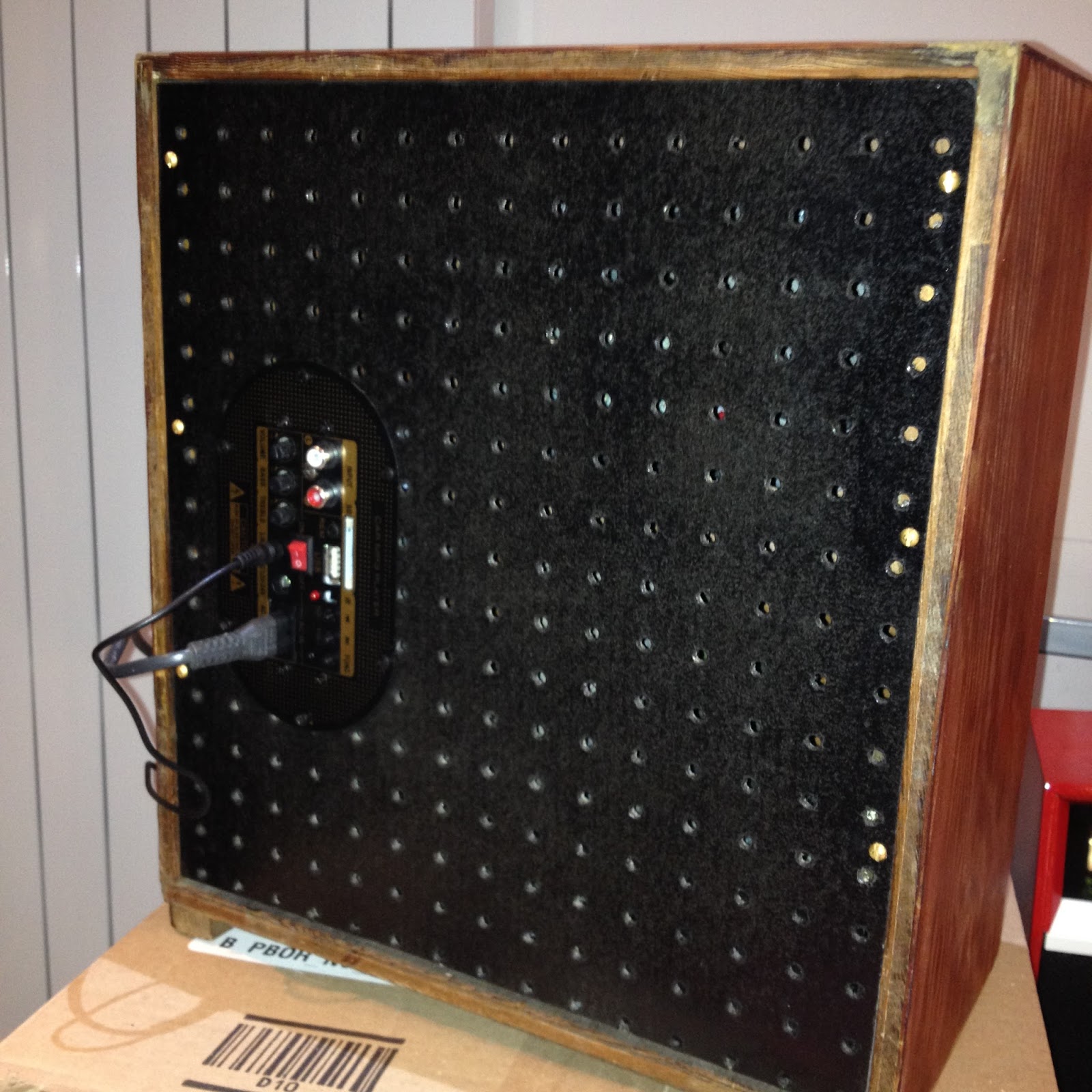
The original back panel was missing, so I made a new one from perforated hardboard; I think its called peg board. I made this the same size as the cabinet, to hide the modern bits I planned to add next.

I fitted a very nice ELAC elliptical loudspeaker. It has a very large magnet for the size of the speaker and appears to be the same as those fitted in the later Hacker Herald transistor radios, which are renowned for their audio quality.

The final part of the conversion (because that it was it had become) was to fit modern electronics. I chose a Chinese made module that combined an MP3 player with a 20W audio amplifier. It will play MP3 files from  an SD card or a USB stick; and there is also a line input with both RCA (phono) sockets and a 3.5mm jack socket. The module will operate from either AC mains or 12-24V DC.

SD Card, USB, Phone & 3.5mm Jack inputs


So how does it sound?  Great! It combines the style and character of a 40's radio with the convenience, sound quality and safety of modern electronics.

I sold this one within days of completing it, so I have now converted the other one as well.  I've made a couple of improvements to this one that I might blog about later.

Keep listening!

Wednesday, January 20, 2016

Bush VHF80c completed

Here's the completed VHF80c sitting on soak test in my workshop tonight.

I'm getting to like this little set, and its later cousin the VHF81. They are easy to work on, and with a bit of effort they can be made to look quite smart.  They are also good performers, with nice quality sound and good sensitivity on AM.

The good AM performance is probably due to the unusual circuit design, in which the VHF 1st IF amplifier doubles as an RF amplifier for LW and MW. In most domestic AM superhets the tuned RF is applied directly to the mixer (frequency changer) valve without any amplification, and all the gain is in the IF and audio stages.


Bush VHF80C after restoration

The trickiest part of the restoration was replacing the four rubber anti-vibration mounts between the tuning capacitor and the chassis, basically rubber grommets with a brass bush through the centre. The old rubber had become hard and brittle. Getting them out was much easier than persuading the new grommets to go in, but at least the new ones should last another fifty years before they need replacing again!

Here's the list of materials that were required to do this restoration.

5 x 10nF polyester film capacitors
1 x 2.2nF  polyester film capacitor
1 x 4.7uF electrolytic capacitor
1 x 0.22uF 275V AC X2 rated capacitor
2 x MES lamp holders
2 x 6V 0.1A lamps
4 x rubber grommets (to fit 8mm hole, centre hole 5mm)
Odd bits of silicone sleeve
2 core mains flex
Mains plug with 1A fuse 
Cord for replacing the tuning drive
White enamel spray paint
Masking tape and newspaper
Brasso for cleaning the Bakelite


With one more done...the question is which set to do next.

Keep listening!


Sunday, January 17, 2016

A nice little set for my kitchen

I've just realised that I didn't post a finished picture of the Bush VHF81 that I restored back in August last year.

I said the colour scheme would be 'something different'... and here it is.

Bush VHF81 with a one-off cabinet

This lovely little set now lives in my kitchen and is regularly used. It has a very good sound, particularly on VHF. Not bad for a set that's around 50 years old.

Keep listening!

Back in the workshop

It's been a while, but now the long dark January nights are with us again I have found time to sort out some vintage radio projects that have built up during the summer.

I've got a couple under way, but the one I have spent time on this weekend is a Bush VHF80c from the early 60's. I don't know its exact age yet, but this model first went on sale in February 1960.

I restored a couple of VHF81s a few months ago, which have the same chassis as this but in a wooden case. I have taken a liking to these sets which are easy to restore and perform rather well, so when I saw this one in a junk shop during the Christmas holiday I had a little haggle with the seller. She wanted £22 initially, but we agreed on a very reasonable £15.

Electronic restoration was fairly straightforward, with three wax paper and three Hunts capacitors to replace. I always replace these on sight as they are almost always leaky. The other job was to reform the reservoir and smoothing capacitors, three capacitors in all in a single metal can. This is a time consuming task as there are a lot of wires to unsolder.


On firing up the set via a lamp limiter I could hear stations on all three bands, so I carried on with restoration of the chassis, replacing the broken tuning cord and the lamp holders. The latter are made of rubber, which hardens with heat and age and goes out of shape. A couple of cheap modern plastic holders and two 6V 0.1A lamps sorted the problem.

This is is an AC/DC set (no transformer) so the mains neutral wire is connnected to the chassis. For safety during testing I always use an isolating transformer to prevent the possibility of the chassis becoming live.


The cabinet was in good condition (apart from being filthy) although the white paint had rubbed away in places over the years, particularly around the knobs.

After stripping down the cabinet I used a fine abrasive paper to smooth the painted areas, before protecting the unpainted Bakelite areas with newspaper and masking tape. I then spray painted all the white areas with a quick drying enamel.


I applied four light coats of paint, leaving each to dry for around 10 minutes between each coat. I now need to leave it to harden for a couple of days before removing the masking and tidying up any rough edges between painted and unpainted areas.

I'll post more later.

Keep listening!

Saturday, September 05, 2015

Cleaning old knobs

Old radio knobs often come with many year's worth of dirt and grime that can be very difficult to remove, particularly from grooved or textured surfaces.

I've found that the easiest and most effective cleaning method is to put the knobs in a solution of biological washing detergent and warm water, and leave to soak for a few hours.

After this treatment most of the muck can just be rinsed off, and a little effort with an old toothbrush will usually shift anything that remains.

This works because much of the dirt will be organic in origin (mainly oils and debris left by fingers). The biological additives in the detergent digest these, leaving the plastics unharmed.

I've used this method many times. So far I've not had any problems, even with knobs with bright metal inserts.

I've just done the knobs for my Bush VHF81. This set is looking really good now, and I'll be putting some pictures in a blog soon.

Keep listening!

Thursday, September 03, 2015

Bush VHF81 Chassis restoration

The electronic restoration of the VHF81 chassis was pretty straightforward. With the chassis removed from the cabinet everything is easy to get to.


Everything looked original, with just five wax paper and two Hunts capacitors to be replaced, including one connected directly across the switched AC input. This was replaced with a X2 type rated at 275V AC. Any other faulty components will be found when the set is powered up again.


The original power cable was replaced with a piece of modern white two core flex. I would usually have used black, but in this case white will fit in nicely with my planned colour scheme. As this is an AC/DC radio, I did a quick check with a DVM to confirm that the neutral was connected to the chassis, and not the live!


The mechanical problems were a bit more difficult. Replacing the broken dial cord took a while. Fitting the cord was reasonably straightforward, although the diagram on the 'Trader' service sheet helped a lot. Getting the tension right was much more difficult, especially when on the third or fourth attempt the tension spring flew off and disappeared somewhere under the bench! Fortunately I had something similar in my junk box, and after a cup of coffee it all came together OK.


The sub-chassis carrying the VHF tuner is attached to the main chassis via anti-vibration mounts; basically rubber grommets with brass bushes through the middle.  The old crumbling rubber bits were replaced with modern plastic grommets. Putting these in boiling water for a few seconds made them just pliable enough to be squeezed, with some difficulty, into the holes in the chassis.


Keep listening!

VHF81 Speaker baffle repair

With the chassis ready for testing I turned my attention back to the cabinet. The original grille cloth was badly damaged and had to go. It came off easily enough, but left behind hard patches of 50+ year old glue which might have shown through the new, thinner cloth

The plywood had also started to de-laminate, and trying to scrape the glue off just made it worse. It did eventually come off with help from a hot air gun, but I had to use automotive cellulose filler to fill the damaged areas of the wood afterwards.


24 hours later I used an electric sander and 320 grit abrasive paper to remove the excess filler, followed by a generous coat of black paint.  It's now ready to receive the new black grille fabric.

I also used some filler on the cabinet, as some scratches were still visible even after several coats of undercoat with light sanding in between them. The first coat of  paint looks good, although I did have momentary doubts over the colour... all will be revealed soon.

Keep listening!

Saturday, August 29, 2015

Something different

The recently restored and repaired Bush VHF81 is currently in my kitchen and in regular use, and it sounds really good.

The only problem is that the mahogany veneer doesn't fit in with my modern kitchen decor!

Lurking at the back of my workshop was another VHF81, purchased from a well know auction site for £15 a couple of years ago. The veneer was wrecked, so I had an idea...


Here's the cabinet stripped of the veneer, filled, sanded, and with a couple of coats of undercoat applied. The next task will be a lot of sanding by hand to get it as smooth as possible, ready to take the top coat.

The colour scheme is going to be unique.

Keep listening!


Sunday, July 12, 2015

Bush VHF81

It wasn't quite as quick a job as I expected, but as it has turned out it was well worth the effort.

As well as 'that' capacitor I replaced all the waxies and the only Hunts cap I could find, and just to be safe I also replaced the 5uF electrolytic in the FM ratio detector stage. I've found that doing this is much quicker than trying to find  faults later.

I also cleaned the diffuser and touched up a couple of damaged areas on the tuning scale with black paint. The scale lamps are both blown, and firmly stuck into the rubber moulded lamp holders. I had heard that this is often a problem with these sets, but I'll sort it out later.

The knobs spent an hour in a solution of biological washing liquid and hot water, which gets years of muck and dirt out of the grooves easily.

Finally I painstakingly de-soldered the wires to all three electrolytics in the can and applied the reformer to each in turn. None had excessive leakage, so there was no need to change it after all.


It's now sitting on the bench playing BBC Radio 2, and it sounds really nice. The only problem is that the tuning scale is working back to front, but investigation into that also will have to wait for another day.

Another success I think. Thanks again to Brian for donating the set.

Keep listening!

The list is getting longer

The 'to do' list of radios awaiting attention is getting longer, and the associated pile of radios has overflowed the workshop bench and on to the floor. As usually happens in the summer, family and social life tend to take whatever spare time the full time job ( the one that pays the bills) leaves me.

The list included a Bush VHF81, a Wartime Civilian Receiver with interesting WD numbers and of course the lovely Pye MM I mentioned in my last blog post.

I wasn't looking for another project at the moment, but this time a radio found me. Well sort of... I visited a colleague who knows of my interest in vintage radio and he very kindly offered me a Bush VHF 81, which I of course I gratefully accepted.

Released in 1964, the VHF81 was the last valve model that Bush made, at a time when most domestic radio production had already changed to transistors. It was based on an earlier chassis, but built into a wooden case instead of its the plastic case of its predecessor. It's not a particularly good looking set, but I've heard good accounts of both its receiver sensitivity and audio quality on VHF.

I was told that the set was working, so assuming that it would be a quick job, I managed to find a bit of workshop time this weekend. So far I've changed the important grid coupling capacitor (aka 'that capacitor') in the output stage and removed loads of dust from the cabinet.

I was told that the smoothing capacitor might need replacing, so the next job will be to get the capacitor reformer out. If it turns out to be duff I might be able to rob the other set for spares, as the capacitor can is smaller than anything I have in stock.

I'll put some pictures up when I get a chance.

Keep listening!

Monday, May 11, 2015

Pye MM

April and May are typically busy travel months for me, and I've had to put my vintage radio restoration plans on hold for a few weeks. That ended yesterday, when I returned from my annual visit to the National Vintage Communications Fair with something rather special.

An early example of a Pye MM

I've wanted one of these for ages! Pye launched this type of set, the MM, in 1932 with a price of seventeen guineas...rather a lot of money back then. This one cost me £50, which I don't think is unreasonable for a complete and original example.

As well as being the oldest set in my collection, this will also be the first Tuned Radio Frequency (TRF) set that I've owned. TRF sets are more tricky to use and less selective than the later Superheterodyne sets, but I'm told that an MM can still be a good performer once restored. With the AM broadcast bands becoming less used, a lack of selectivity won't be as much of a problem today as it might have been in the past!


Side view showing controls

I’m hoping that the mechanics won't be to difficult to sort out. Pye used a die cast alloy called Mazak (also known unkindly as monkey metal) in sets of this period. Unfortunately Mazak is now known to weaken and even disintegrate with age. Several major mechanical parts in this set are notorious for either becoming distorted over time, or breaking when handled during a repair.

Although described as a transportable, this is quite a large and heavy set, and definitely not something that would go unnoticed in a modern room. Fortunately my wife loves the simple but iconic design as much as I do, and it will become part of our increasingly vintage decor.


Rear view showing hinged door.

The cabinet is in quite good condition and there's no sign of woodworm, either past or present. There is a small bit of damaged veneer, and the french polished finish has seen better days. Both of these may get some specialist attention.

I don't expect to be doing much to this soon, as my other (paying) work is piling up. And then there is also the matter of a Wartime Civilian Receiver cabinet and chassis that also followed me home from the NVCF. These now look like they may be more interesting than they first appeared, but that's a story that will have to wait for another time.

That's it for now, but keep listening!


Saturday, March 21, 2015

Clansman radio reverse polarity protection

The Clansman PRC320 HF man pack radio was designed to be used with detachable batteries, either clipped onto the transceiver body or connected remotely via a battery extender cable. In either case the battery can't be connected incorrectly, so there was no need to include reverse polarity protection in the radio.

Clansman battery & extension cable
For amateur radio expeditions I like to power my PRC320 from a pair of car batteries, connected in series to provide the required 24 Volts. I modified a battery extension cable by cutting off one connector and fitting a pair of crocodile clips in its place. Unfortunately it would be very easy to accidentally reverse the polarity and cause a lot of expensive damage to the radio.

I could have put a diode in the lead, which would have caused a small voltage drop, but instead I decided to use a polarity sensing relay. This has a diode in series with the coil; if the supply is connected incorrectly the relay doesn't operate and power isn't applied to the radio. Of course the relay takes additional current from the battery, but with the very large (around 100A/h) batteries that I use this doesn't actually matter!

Here's the relay box that I built.I wasn't going to fit a switch, but then I found an RS 10A resettable circuit breaker in my junk box. This avoids the need for spare fuses, and also works as a switch.

Internal view


Resettable circuit breaker and power LED

The diecast box cost me around £5 at Maplin, and all the other bits came from recycled equipment. 
The cost of building one like this from all new components (but not including the Olive Drab paint) would probably be around £20, which would still be much less than the cost of repairing the radio after an accident!

Wednesday, February 18, 2015

Radionette revisited...and fixed.

I've not had an opportunity to spend time in my workshop for a couple of weeks, but I did find time today to have another look at the Radionette Kurer valve portable.

With the faulty set tuned to 1000 kHz on the medium wave band I was able to pick up a strong 1455 kHz signal on another set next to it on the bench. This confirmed that the Kurer's Local Oscillator was running. I tried injecting a modulated 455 kHz test signal again, coupling the output from my signal generator into the set via a few turns of wire around the DK96 valve. Instead of the pure tone that I expected, there was a beat note from the speaker.  This usually indicates an unstable and oscillating IF stage.

Turning again to the internet, I found several references to similar faults with battery sets in various vintage radio forums. I had already changed the decoupling capacitors and checked screen resistor values, which left possible problems with poor contacts in the valve bases. I gave both mixer and IF amplifier valve sockets a liberal application of contact cleaner spray, and again following suggestions in a forum post, tightened up some of the contacts in the sockets. The advice turned out to be spot on, because on powering it up again I could immediately hear received signals.

It's currently sitting on the bench playing my local AM station on 1332 kHz. The sensitivity isn't great, and i'ts pretty deaf on long wave as well.  I'm assuming that this is because the loop aerials aren't connected, so I'll try it again once its back in the case.

It's been an interesting repair job, but I can't honestly say that there is anything about this set that I like. I'll be quite happy to hand it back to my friend.

Keep listening!


Thursday, February 05, 2015

Pentagrid Converter

The Radionette Kurer is a step nearer to working but I've run into a problem. Apart from an intermittent volume pot the audio stage is operating, but the receiver is otherwise dead on all four wavebands.

The IF and detector stages are also working, because a modulated 465kHz test signal can be heard OK from the speaker. My next thought was that perhaps the Local Oscillator wasn't running, and this was where I began to struggle a bit.

All of the receivers I have worked on have either had separate oscillator and mixer valves, or have had these two functions combined into a valve with two distinct sections, typically a triode-hexode such as the ECH81. This one uses a single DK96 heptode valve as a self oscillating mixer. Here was the problem; I'd never seen this configuration before and I couldn't understand how it worked.

The answer came from Wikipedia in an article entitled Pentagrid Converter. This explained how the first grid is used for the oscillator, with the second grid acting as an anode.  The incoming RF signal from the antenna tuning circuits is applied to grid 4. The remaining grids 3 and 5 are connected together to act as screen grids. Grid 2 allows some of the oscillating electron stream to leak through and couple with the mixing section of the valve.

The Wikipedia article can be found here.

The only circuit diagram I have for this set is a very small picture pasted inside the rear cover. I don't have any component layouts or test voltages either, so given my unfamiliarity with this type of circuit this one it's going to be a bit of a challenge!

I need to spend a few days away from the workshop so regrettably this job will have to be put away for a while, but before I do I will check if the LO is actually working. The easiest way to do this will probably be to use another radio. The LO will be running 455kHz above the receive frequency, and should be receivable on another radio in close proximity.

Keep listening!


Radionette Kurer


It looks like my interest in vintage radios has influenced one of my friends, because he turned up at my house recently with an unusual radio that he wants me to restore. I forgot to take the usual 'before' photo, so here it is almost as received, but without its knobs.


The Radionette 'Kurer' is one that I'd never even heard of before. It's a battery/mains portable from Norway with Long, Medium and Short wave bands, and I would guess that it dates from the early to mid 1950s. It's complete and in reasonable condition, but one of the knobs has lost its brass trim and another is cracked.


The set uses 'D' series battery valves which require 90V for the HT, and 1.5V for the filaments. Batteries for valve radios haven't been made for decades, so the chances of finding a serviceable one today must be very low indeed. Fortunately the mains winding on the transformer seems to be OK, so at least this set should be usable.

It took me a few minutes to work out how to remove the chassis from the cabinet. Eventually I realised that  the wooden panel onto which the chassis and transformer are mounted slides out.

The wires on the left side of the chassis are connected to a aerial  inside of the cabinet.


After the usual strip, dust and clean the first task will be to replace some of the capacitors. Although there aren't any wax paper capacitors in this set there are several brown 'Hunts' branded ones, which in my experience can't be trusted either and usually get replaced on sight.

The smoothing electrolytic is only rated at 150V working. My capacitor re-former won't go this low so this time I will have to bring the supply Volts up slowly using a variac. This trick doesn't work well with sets which have a valve rectifier, but fortunately this one uses a selenium rectifier in the HT supply which will work at low supply voltages.


 I'll let you know how I get on.

Keep listening!

Wednesday, February 04, 2015

Visit Counter

When I changed the blog layout in February last year I lost the site visit counter. I've finally figured out how to add the HTML code back  into this layout, so as of today there is a Site Meter counter at the bottom of the page.

I've reset the counter to zero today, so it will be interesting to see how many visits this blog is actually getting.

Keep listening!

Monday, February 02, 2015

A bit of HRO history

A couple of people have asked me why I find the HRO receiver interesting enough for me to have two in my collection.


I'm interested in World War Two history, and in particular the code breaking activities of Bletchley Park. The HRO played a very significant role in this work as it was the standard receiver used for intercepting the encrypted German radio traffic.

The HRO has its origins in the mid 1930's. The National Radio Company of Malden, Massachusets had previously produced a receiver for the aviation industry, known as the AGS. The successor to the AGS was intended to meet the needs not only of airlines and commercial users, but also Amateur (Ham) Radio Operators who wanted a very high performance shortwave receiver.

The HRO was brought to the market very quickly, and it's name may reflect this. It is said that staff who worked on the project  wrote 'HOR' on their timesheets, meaning 'Hell Of a Rush'. Apparently National thought HOR was inappropriate, and rearranged it as HRO (subsequently said to mean 'Helluva Rush Order'). It went on sale in 1935 at a cost of around $200, which must have been a lot of money at the time!


Very early in WW2, the War Office decided that the receivers in use by British armed forces might not be good enough for the anticipated needs of the war, and a search for a better and commercially available receiver was undertaken.  A number of types were evaluated but the National HRO was considered to be most suitable. At first the British Government was not able to buy HROs in quantity (I assume this was when the USA was neutral), so British officers traveled to the USA to buy sets and import them personally. Many thousands of HROs were subsequently sent to Britain under the Lease-Lend arrangement, and there were probably more than 10,000 in use by the end of the war.

HROs were used as a general purpose HF receiver by all British Forces. The 'Y' stations (I believe the name came from Wireless Intercept, or WI) operated by the Army, Royal Navy, RAF and the Radio Security Service all used HROs. They were also issued to civilian Volunteer Interceptors, who used them at home under control of the RSS.

RSS intercept station at St Erth, Cornwall.

The HRO was very advanced for its time. There were several versions produced over the years but due to its superb performance and ease of operation, even the early ones remained in use by both commercial and military users into the late 1950s, and possibly later. After the war many came onto the surplus market and were eagerly bought by Amateur Radio Operators, and HROs were prized posessions in many radio shacks for several decades. In fact, the first one I ever saw was in the shack of a local Ham who introduced me to the hobby around 1975.

There are a number of good websites where information on HRO receivers can be found. One of the best in my opinion ( I have no connection with it) can be found here

Keep listening!


Thursday, January 29, 2015

HRO MX update 4

The HRO powered up and made noises on the first attempt, but I couldn't actually tune in any stations with the 180-400 KHz coil pack installed. However with the 0.9-2.0 MHz coil pack installed (the only other one I have at present) it was a different story! 


It's currently sat on the bench playing Smooth Radio on 1332kHz, and a quick tune around found a few European stations as well. I'm well pleased! 

I hadn't planned an external restoration, but it will get a thorough clean and tidy. The worst of the chips and scratches will probably get filled with black paint.

My next task will be to get some coil packs for other frequency bands. AM broadcast stations are ok to prove the basic operation, but I want to see how it copes with CW and SSB signals on the amateur bands.

Keep listening!

Wednesday, January 28, 2015

HRO MX update 3

Whilst checking components above the chassis, I noticed that the connections to the Local Oscillator coil have been modified.

One of the coil contacts was originally connected to a capacitor mounted on a ceramic insulator on the chassis. I believe that this provides temperature compensation.


This connection has been broken, and in its place are an additional inductor and variable capacitor below the chassis. These form a series tuned circuit between the coil connection and ground.


I've no idea what the purpose of this modification might be, and a quick search on the web didn't turn up anything relevant. I somehow doubt that it's an 'official' modification though.

I'm tempted to remove it and restore the the original circuit, but I think I'll do a bit more research first.

Update: Having failed to find any info on the modification, I decided to remove it and restore the original wiring. 

Keep listening!