Saturday, December 20, 2014

GEC set update

After a busy few weeks that have kept me away from the workshop, I finally found some time to spend on the GEC BC5645, which has been stuck on my bench for quite a while now. All the usual suspects and anything else that appeared to need replacing have been taken care of, and the set had been powered up via the lamp limiter and the HT voltages checked.

Chassis ready to test, with temporary connection to Gram socket

It didn't burst into life initially, so a bit of basic faultfinding was needed.

All the voltages on the EL84 output valve looked OK, and a test signal injected into the grid of this valve gave a nice clear tone from the speaker. Injecting the same audio onto the volume control gave a very weak and intermittent audio, with lots of crackling.  The output from the volume pot feeds the grid of an EBC90 double diode triode, which performs the triple role of AM detector, AGC detector and audio preamplifier.

The anode and grid voltages looked OK, but the valve seemed to be very microphonic and gave a terrible noise from the speaker when handled. A quick swap with a new valve was tried, after which the set was completely silent!

After a few minutes poking around the valve base with a meter I began to suspect the socket was the problem. A couple of shots of de-oxit cleaner spray didn't appear to help much. Pulling out the valve again, I had a good look at the socket from above with a magnifying glass and....mystery solved.

B7G valve socket after cleaning & adjustment

Most of the contact pins seemed to have been bent, so that the contact with the valve pins wouldn't have been as good as it should be. With the aid of a very fine pair of tweezers I closed the two fingers that form each the seven contacts together, in the hope that this would grip the valve pins better. I then put the original EBC90 valve back in.

The bodge worked, and the test tone applied to the volume pot was loud and clear from the speaker. At least the audio stages are working!

It's now playing music loudly from an MP3 player connected to the gram input. It remains completely silent on both AM and FM, so more investigation will be needed.

Keep listening!

Friday, November 28, 2014

Even more radios!

A few weeks ago I decided to pick up a few more sets as 'winter projects'.  I now have a couple more than I originally intended, and the workshop is now overflowing.


National HRO HF receivers

The latest acquisition (the black one in the picture above)  is a National HRO MX, a classic HF receiver that was used extensively in World War Two. The design originates from the 1930s; I haven't had chance to do much research on this particular one, but I think it was probably built around 1942 onwards.

There were tens of thousands of these in use by British forces during the war and for some time afterwards. As a result they are not particularly rare, but finding one that is complete and unmodified can be difficult. This one is complete apart from its power supply, which was a separate unit.

The blue radio is also an HRO that I bought in 2013, but so far I've not been able to find out much about it. The person who restored it assured me that the colour was the same as the original, or as close as he could get.  It might be a variant known as the RAS which was used by the navy, but that tale will have to wait for another day.

I'm looking forward to starting work on the HRO-MX after Christmas, by which time there should be sufficient space in the workshop again.

Keep listening!

Tuesday, November 18, 2014

BC5645 Chassis

I spent a couple of hours working on the chassis tonight. I still haven't applied power yet, but all suspect components including Hunts capacitors have now been replaced.

Someone had obviously done some work in the past, as several of the capacitors had already been replaced. I think the ones left were those that were difficult to get to!

Three capacitors
It wasn't particularly easy, as most components that connect to ground have been soldered directly to the chassis, instead of a solder tag bolted to it. These connections take a lot of heat, and getting a big soldering iron in without overheating adjacent components was a bit of a challenge. Where possible I left a bit of the old component leg in place and soldered the new component to it; it's not as neat as I would like, but it does guarantee a good connection.


Fortunately none of the components in the VHF section required replacing, as longer leads here might cause problems.

Finally all three sections of the reservoir and smoothing capacitors reformed without problems. The next stage will be to apply power, and I'll update the blog then.

Keep listening!

Sunday, November 09, 2014

Work in progress

A bit more work today has made the BC 5645's cabinet look pretty good.


The baffle is back in place, and properly secured with the repaired mountings. The grille fabric isn't the same colour as the original, but it's in keeping with the age of the set. I think it looks OK, certainly better than the fabric it had when it arrived.


The inside looks much better too. The red blobs are paint, intended to secure the screws. They were originally painted white; I'm wondering if this was just a cost saving measure, as paint was probably cheaper than shake proof washers?

The final job was to touch up the odd scratches and chips that were letting light  through the glass tuning scale. A quick dab of Matt black acrylic paint on each damaged area does the job well, and can't be seen from the front.


Apart from a good polish, that's the cabinet done. The next job is the electronic restoration of the chassis.

That's all for now.

Keep Listening!

Saturday, November 08, 2014

GEC BC5645

After many months of distractions, I finally got round to starting the BC 5645 today!

It's not in bad condition, although the Bakelite cabinet is going to need a lot of polishing to reduce the visibility of some scratches.

The chassis came out first so that I could give the inside of the cabinet a good clean. Two of the baffle board mounts had broken off; one was in the bottom of the cabinet but unfortunately the other has been lost.


Next to come out was the baffle and speaker, and then, after a good clean and vacuum, I glued the broken mount back in place. A 2BA bolt with the head set in Araldite replaced the missing mount on the other side.

The speaker cloth has seen better days, so this also came off and will be replaced with some new fabric.


The chassis had a light coat of rust in places, but a bit of effort with a brass brush removed most of it.

The only mechanical part of the chassis that will need replacement is the curious paper diffuser for the tuning scale. This is held under tension with spring adjusters. Most strange!


It looks like some restoration work was done on the chassis some time in the past, as several of the infamous Hunts capacitors have been replaced. There are still four or five left and these will have to go, along with the one remaining wax paper capacitor.


More updates will follow soon, so....

Keep listening!

Thursday, November 06, 2014

New Arrivals

With the arrival of cold weather and dark nights my thoughts have turned to getting some radio projects organised for the winter months. Two more sets have now joined the the GEC BC5645 in the 'to do' list.

This Bush VHF81 arrived last week. It dates from the latter half of the 1960s, which makes it one of the last valve sets to be made in Great Britain. As the name suggest, this one includes VHF FM in addition to the usual MW and LW bands.

I haven't got round to taking any photos yet, so this picture is from the listing on the auction site.

Bush VHF81

I hadn't planned to acquire any more radios at the moment, but I couldn't resist going for an Ivory coloured DAC90A that nobody else was bidding on. I've fancied one of these for a while now, but being less common than the brown ones (which aren't rare at all!) they usually fetch a much higher price.

I was delighted to win it for the starting bid of £30, which is less than the profit I made in selling a brown one recently. It's supposed to be working, but will still need the usual electronic restoration and safety modifications.

It hasn't arrived yet, so this picture is also from the listing on the auction site.

DAC90a
Three sets in the workshop should provide enough work to keep my evenings busy for a few weeks.  I just need to buy in some components before starting with the GEC set.

More updates will follow soon so...

Keep listening!


Saturday, October 11, 2014

Another one completed

The Bush DAC90A is finally complete and on its way to a new home.

The final fault that had to be sorted was a duff volume control, which cut out at a point around three quarters from full volume.

No amount of cleaning made it any better, even after I stripped the pot down to expose the track. Luckily I had was able to get a similar potentiometer for £3, which had the added advantage of an insulating plastic shaft.

The audio distortion I noticed earlier was cured by giving the speaker a really good clean to dislodge a load of dirt and muck that had built up between the chassis and cone.  There were also a couple of tears in the speaker cone which required a bit of glue to stop them tearing further.


After a good clean and polish of the case it looked great, and ready for many more years use.

More radio recycling tales will follow soon.

Keep listening!

Saturday, October 04, 2014

DAC90A valve failures

The DAC90A powered up without anything unpleasant happening, but it was obviously not receiving anything. I switched the power off for a few minutes while I made some room on the bench, but when I switched it back on again it was completely dead. None of the valves heaters were lit.

After a few measurements with the ohmmeter I found that the heater of the UY41 rectifier valve was open circuit...most strange, because it had worked initially. I pulled out the duff valve and happened to notice some movement inside it.  The wire that connected one end of the filament to pin 1 had become detached. I've never seen this sort of valve failure before! Fortunately I had a scrap Ekco set in the garage which has the same valves, so I had a spare on hand.

On powering up the set again, all I got was a little hum and noise from the speaker. Touching the wiper of the volume pot with a screwdriver gave a nice loud hum, so the audio stages were obviously working.
I fired up my AVO Allwave Oscillator (a previous restoration project) and poked a 465 k/cs signal into the IF amplifier valve grid.  Nothing happened. With suspicion now firmly on the IF section, I checked the anode Volts of the IF amplifier valve and found they were a bit high, suggesting that the valve wasn't doing much work.

At this point I decided to take a short cut and just change the UF41 IF amplifier valve for one of the spares I had just liberated from the scrap Ekco. As I pulled the valve out of the DAC90A, I noticed something funny; there was a lot of white debris inside the valve!

If you look at a radio valve you will normally see a silver coloured deposit  inside the glass, usually at the top. This is created during manufacture, and is the result of a process which removes any gas that remains inside the valve.  If this silvering changes to white, its a good indication that air has got into the valve. In this case the white substance fell to the bottom of the valve where it couldn't be seen easily.Otherwise the valve looked OK.

Another UF41 was fitted, and the radio started to work. Here's a picture of it on the bench, tuned to Smooth Radio, my local AM station. The audio is a bit distorted, so I will have to investigate this further.

More to follow soon

Keep listening!

Bush DAC90A progress

The DAC90A has been in my workshop for a couple of weeks now. I've not spent as much time as would have liked on it, but it is coming on well.

After cleaning up the chassis and removing the valves for safe keeping, I started off by replacing all the wax paper capacitors and a lot of the wiring. This included the wiring around the mains dropper, the dial lamps and the loudspeaker wiring.

The flexible wires were replaced with modern silicone insulated wire which looks very much like the original rubber insulated stuff.  With solid core wires I just snipped one end, pulled off the old rubber, slid a new silicone sleeve in its place and then re-soldered the wire in place.

Dial lights & reflector removed for easy access

Several  high value resistors measured considerably higher than their original value, and I replaced any that were outside a 20% tolerance. The 2.2MΩ resistors in the AGC circuit were way beyond this, nearly 3MΩ.

I spent a while reforming the smoothing capacitors before applying power. I did this with the capacitor in place, with the negative tag disconnected from the chassis.  When I started restoring old radios, one of the first items of test equipment I built was a capacitor re-former, which applies the capacitor's working voltage via a current limiter.

Reforming the smoothing capacitors

Both the 16uF and 32uF sections of the smoother reformed well, the initial leakage currents of around 5mA dropping to less than 1mA after around 30 minutes of reforming.

I fitted a two core mains lead, ensuring that the neutral was connected to chassis. A test with the multimeter between neutral and chassis gave around 5 Ohms  (the combined resistance of the the dial lamps and the bypass resistor). This check is very important to avoid a live chassis!

New components & wiring

I always use a mains isolating transformer when working on an AC/DC set.  I also used my lamp limiter when applying power first time, if there had been a problem the lamp would have lit and reduced the current somewhat.  All was well, so I took the lamp limiter out of circuit.

I'll tell you what happened next in the next blog entry.

Keep listening!

Tuesday, September 23, 2014

Another DAC90A

Whilst I was on holiday recently I picked up another Bush DAC90A.  I did say that I wouldn't buy another unless it was white or ivory colour, but at £15 I just couldn't turn it down. It will probably go to a family member or friend once its been restored.

DAC90A in as-found condition
It's complete and appears to be unmolested...no sign of the phantom bodger here! There is a tiny chip in the bakelite underneath, but apart from being filthy the cabinet looks OK, so its a good candidate for restoration.

 The rear panel is a bit rough, but should be usable after a good clean.
The glass is intact and undamaged

The only thing I want to check before starting is the loudspeaker output transformer; these have been known to fail, and it can be difficult to find replacements. This is one of the things that can happen if someone has found the set and just plugged it in to see if it works.

Finally, a couple of 'before' pictures of the chassis. There's a good sixty year's worth of dust and muck on it, but no sign of moisture damage. There's a little rust on the lamp holders, but no much anywhere else.

Six decades of dust

The smoothing capacitor is dated November 1954, so this set was probably built late in '54 or early '55.

I've seen a LOT worse!

The only problem I have now is making room for it in the workshop. The GEC 5645 is supposed to be next in the queue, but DAC90As are relatively easy to work on and it could be a quick job. I'll let you know how I get on later.

Keep listening!

Tuesday, September 09, 2014

Clansman PRC320 repair

The Clansman PRC320 HF radio that I recently blogged about has been in my workshop for repair this week. It failed when I took it on holiday early in August, but I hadn't had time to fix it until now.

The set appeared completely dead and wouldn't power up, even though I tried two freshly charged batteries.
It turned out that a screw had worked loose, and it had ended up being lodged between the +24V battery input terminal and the chassis.

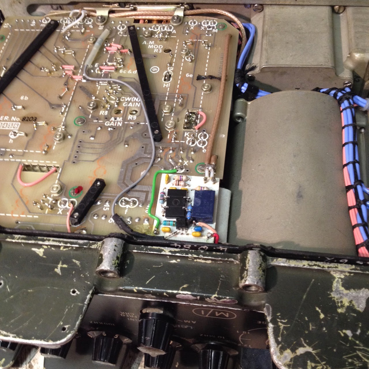
PRC320 main PCB, with LSB modification  installed

The offending screw was one of the PCB securing screws which are identified with a green circle on the PCB silkscreen. Its now back in place, centre left of the photo above, and secured with a dab of the wife's red nail varnish.

The little white PCB in the photo above is the LSB modification that I recently fitted. I might detail this in a blog some other time.

If you open up one of these sets yourself it would be a good idea to check all the screws for tightness. Quite a few were loose in mine, along with the nuts securing the BNC sockets on the rear panel.

I later discovered that the dead short had taken out both of the batteries. It appears that they have an internal fuse (probably a good idea if one is going to put a dead short across a large pack of NiCd cells) but unfortunately it is buried deep between the cells where it is inaccessible.

Clansman 24V 4Ah NiCd battery

The battery packs were the later all plastic types and arent meant to be opened, but I was able to prise the bottom off of one of them. I exposed the bottom layer of cells by digging out some of the foam that surrounds them, but I didn't think I would get any further without damaging either the cells or the plastic case.

The thin red and black wires in the centre of the pack are from one of the temperature sensors used by the charger.

I've still got one good battery pack left. That should keep me going for now, but in the longer term I'll either have to buy some more, or come up with and alternative form of battery.

Keep listening!


Sunday, July 20, 2014

Clansman military radios

Clansman was the name given to a Combat Radio System used by the UK armed forces from the late '70s to around 2009, when it was replaced by the current Bowman system. It comprised a range of man portable and vehicle mounted radios in the HF (2 - 30MHz), VHF (30 - 76MHz) and UHF (225 - 400MHz) frequency bands.

The HF and VHF versions are of interest to radio amateurs for the HF, 6M and 4M bands and are becoming very collectable. The UHF kit is AM only, and has no real amateur radio application. Disposals by the Ministry of Defence have now ceased and inevitably the price of available kit has begun to rise significantly. 

I acquired my first Clansman radio, a PRC320 HF man-pack, around a year ago. It's an excellent piece of kit, although it is heavy and somewhat basic compared to commercial and amateur transceivers. It is however extremely rugged and can be thrown around, used in the pouring rain or have beer spilled on it without suffering any damage.

A PRC320 similar to mine, with whip antenna connected.
The PRC320 was primarily designed as a man portable radio but it could also be installed into vehicles. The original military uses were to provide ground wave communications over short distances using either the whip antenna or an end-fed vertical, or sky wave communications over greater distances using a dipole.

The built in Antenna Tuning Unit is somewhat limited and will only work with the whip or end fed wire antenna. Dipole antennas are assumed to be resonant on the frequency in use; these are connected directly to the transceiver, bypassing the built in ATU.

My 320 in fixed-station use during a recent camping trip

For amateur radio an external ATU (in my case an MFJ-949e) is useful and will allow a wide range of antennas to be used with the PRC320. The maximum RF output is 30W, on CW, AM or USB.  One of the most common modifications is to add LSB; there are various was of doing this, most of which apparently work very well.

As with any form of electronic equipment, older examples may need a bit of work to restore reliability; some Clansman radios are 30 years old, and even military grade components can degrade in this time! To a fan of radio restoration, this is part of the fun in owning kit like this.

There are a number of excellent websites and user forums covering repair, modification and use of Clansman radios, so I won't add to them here. I have come up with a couple of modification ideas of my own, so these will get blogged later.

Keep listening!

Sunday, June 01, 2014

Oops I did it again

I saw this lovely Hacker Herald VHF set at the Spalding Radio Rally today. It was getting late and the traders were keen to get everything sold, so when I was offered it for only £5 I just had to accept!


It could do with a clean and a little TLC to the trim on the handle, but all that was needed to get it working was a couple of new PP9 batteries.

It sounds great too, so now I'm enjoying a beer whilst listening to Johnny Walker on BBC Radio 2.

Keep listening!

Saturday, May 24, 2014

My radio collection, May 2014

Since I bought my first vintage radio just over a year ago, my collection has grown much bigger than I had originally intended. I've been meaning to post some pictures and details for a while, so here they are.

Ekco A104, 1949/50

I bought this in non-working condition for £15. My first project, this set is now fully restored and in daily use in my workshop.


Pye P75, 1953

This Pye P75 was my second project, and was a much easier job than the Ekco. The original Celestion speaker had seen better days, and was replaced with an identical unit in good condition. I have done the usual component replacements but I've left the cabinet as I found it.

Bush DAC90A. 1954

I paid £35 for this in May 2013, it was sold as working but needed a re-cap and  re-wiring, especially around the mains dropper which runs fairly hot. Now fully working, this one gets used fairly regularly.

Ferranti 545, 1954.

Another auction item, this time won for £15. This lovely little set needed the usual re-cap and attention to the wiring to get it back to full working order. The painted parts of the cabinet had to be redone, but fortunately the veneered areas were almost perfect and were left as original.


Wartime Civilian Receiver, 1944.

I wrote about my restoration of this set elsewhere in this blog. Now fully working, this set is displayed in my living room alongside my 1940s bakelite phone.


Bush SUG91, 1947

This has just been finished, and is currently on test in my workshop. This set has been my longest and most expensive restoration project so far, but the end result is worth the effort. It's probably the best sounding AM radio I have ever heard, due largely to its 10" speaker and huge console cabinet. I bought this with the intention of selling it once restored, but I like it too much!


GEC BC-5645, 1956

This is the most recent addition to my collection, and is still as I bought it. I'm looking forward to restoring this one as it will be the first one with VHF FM. I paid £10 for this set, which was very reasonable given its excellent condition.

No doubt there will be more added in the future, so if you are interested please come back again.

Keep listening!

Thursday, May 15, 2014

Back to Life

It's been a while since I was able to spend some time in the workshop, but today I managed to set aside an hour or so to look at the Bush SUG91 chassis again.

After a bit of coaxing, it's now sitting on the bench playing Smooth Radio on 1332kHz. The wave change switch is very intermittent though, even after a good dosing with Servisol.  


The only slightly worrying thing is a significant frequency drift. In the last 20 minutes or so I've had to re-tune it slightly several times. I suppose that this might be due to the dodgy switch, (or perhaps because because I gave the oscillator section a good soaking with switch cleaner!)  I'll see what happens if I leave it on test for a while. 

At least I'm one further step towards finishing this one. The restored cabinet has become a permanent fixture in the kitchen, but fortunately my wife likes it.

Keep listening!

Monday, May 05, 2014

Another project

 I did say that I wouldn't buy any more radios, at least until I had finished ( and possibly sold) the current projects.

However, following a trip to a Bank Holiday car boot sale, I now have a GEC BC5645  from around 1956 to add to the 'to do' list!


At £10 it was a pretty good deal; it looks like it's complete, and without any damage to the bakelite or plastic. It's also got VHF FM, which none of my other vintage radios have.

Keep listening!

Friday, April 18, 2014

The sound of silence

Well the replacement CL33 valve arrived safely via Royal Mail (even though the package wasn't marked as fragile) and earlier today I had another go at powering up the SUG91 chassis.

The valve heaters glowed once again, and the HT came up to around 245V on the rectifier cathode. Everything began to look good, but the loudspeaker remained suspiciously silent. After a couple of quick checks with the AVO it became obvious that the primary of the output transformer was open circuit!

I thought that I had checked that earlier in the restoration... but perhaps not.

I'm a bit suspicious that both of the faults have been around the output stage. Perhaps the valve suffered a catastrophic failure (excess grid current caused by a leaky capacitor perhaps) and took out the transformer?

So now I'm looking for a replacement, and the radio will have to stay unfinished for a while longer.

Keep listening!

Sunday, April 13, 2014

Not quite as I hoped...

I had hoped to get the Bush SUG91 completed this weekend, but unfortunately I found a fault that had not been picked up during the restoration.

On powering it up for the first time (via an isolating transformer, because in this set mains neutral is connected to chassis) I was greeted by a nice bright pilot lamp, but no glowing valve heaters. All the valve heaters are wired in series, and as expected one was open circuit;  unfortunately it was the  CL33 output pentode, which I don't have in stock.

I managed to get one from the usual internet auction site, so hopefully in a few days I will be able to get it working.

I did manage to finish the cabinet though, and I'm very pleased with how it looks.


I've deliberately left a few blemishes and imperfections, as I wanted it to look used but cared for, rather than brand new.  I was thinking of selling this one when it was finished, but now I like it so much that I might keep it.

Details of the electronic restoration will follow, so come back later if you want to know what it took to get this one working again.

Keep listening!

Friday, April 11, 2014

Fixing Woodworm Holes

I mentioned in an earlier post that my Bush SUG91 cabinet had suffered from woodworm sometime in its history.

During restoration of the cabinet I realised that if I filled the holes with wood filler, the filler would be a different colour than the surrounding wood after I had applied wood stain.  I believe that some types of filler will take a stain, but not any of the ones that I had in my workshop.

My wife came up with a brilliant idea; dip a cocktail stick into PVA glue, she said, and poke the stick into the wormhole. Once the glue dries, cut off  the stick close to the surface of the wood, and sand down whatever remains standing proud.

Brilliant idea! It worked really well, and after applying the stain the repairs are almost invisible.

Keep listening!

Bush SUG91 Cabinet Restoration

The old damaged veneer came off easily. After using a heat gun to gently soften the glue, I was able to peel the damaged veneer off with a craft knife blade. A quick sanding removed all traces of the old glue and left a smooth surface ready to accept the new veneer.

Damaged veneer removed

One large piece was fixed onto the top surface using PVA glue. I then clamped another piece of wood on top to keep the veneer flat whilst the glue dried.  For the two curved surfaces I used contact adhesive, as clamping these in place while PVA dried would have been very difficult. The glue I used allowed a small amount of movement before bonding firmly, and I cut the veneer to shape as closely as I could before applying the glue.


Top and one side complete

I allowed the glue to dry overnight before carefully removing the excess veneer with a very sharp craft knife blade. The rough edges were then sanded down using fine sandpaper on a wooden block.

This was my first attempt at applying veneer, but on reflection it went better than I had expected. The finished result looked pretty good, although I didn't get a perfect clean edge between two joining pieces on the top surface. A lot of sanding was required to get a smooth surface ready for lacquering

.
After staining
The cabinet sides and bottom panel originally had a very dark brown lacquer finish. Unfortunately the new veneer is a different shade than the original, so to reduce the final  number of colours I decided that a new colour scheme was needed. The front and control panel were just sanded and re-lacquered; all other surfaces were treated with dark oak stain before lacquering.

Once the lacquer has hardened I will give it a polish and then start re-assembling.  I'll post more details and photos later.

Keep listening!

Tuesday, April 01, 2014

Another Bush radio

I picked up a Bush SUG91 radio for £10 in December, and its been sitting in my workshop ever since. I believe that this type of floor standing sets were known as 'console' sets. It's a big old beast, but with its 10" speaker and large cabinet I'm hoping it will sound good.

This is the first set in my collection that I have been able to date exactly; a quality control label inside shows that it passed its final test on 27th January 1947.  

The chassis looks very similar to a Bush DAC90, but with the addition of shortwave and a gram input. The SUG91 is an AC only set, but with an auto-transformer instead of a proper double wound transformer. I'm not sure why this was, as the cost saving must have been very small.  (There was also an AC/DC version called the DUG91 which used a dropper resistor)

As with AC/DC sets though, the mains neutral is connected to chassis, so it will need the usual safety precautions taking. There is plenty of space in the cabinet, so I might fit an isolating transformer inside if I can find something suitable.

Bush SUG91 radio

I can't find the photo that I took before starting work, so this is one of a similar set from the internet. The cabinet was in pretty good condition, but there were a few woodworm holes in one side, and an area of damaged veneer on the top left front edge. I don't think there were any live woodworm left, but just to be safe I gave it a good soaking with woodworm killer, wrapped it in a plastic bin liner and left it in the garage for a few days before bringing it into the house.

The chassis came out a few weeks ago. since then it's been cleaned, re-capped and had some wiring replaced. Over the last few days I have stripped down the cabinet, removing the speaker baffle, control panel and the decorative trim round the tuning scale; these all came out easily after removing screws.

Removing the damaged veneer was easier than I expected, but getting the old lacquer or varnish off has been a bit of a problem. I think I'll leave that story for another day.

Keep listening!

Saturday, March 29, 2014

Radio Recycling

As from today the name of this blog has changed to Radio Recycling.

For the last couple of months I've been blogging about my interest in repairing and restoring vintage radios, so an update was required. (The old name dated back to 2006 when I was presenting a 1980's themed radio show and never got changed)

Thanks to a change in my employment status it looks like I might have a bit of spare time over the next couple of weeks, so expect a few other changes here with the old posts being cleared out, and perhaps a new layout as well. The blog address will also change, as soon as I work out how employ my new domain name radiorecycling.co.uk

My current project is a Bush SUG91 console radio, which was built in January 1947. Restoration of the chassis is almost complete, so some project related posts and pictures will also be appearing here soon.

Keep listening!

Monday, March 24, 2014

Wartime Civilian Receiver - Part 5: Finishing touches

With the set working again, the final part of the restoration entailed making replicas of the top panel and rear panel labels, and sticking these onto the cabinet.

Top label in place

The design for the top panel label was available on the web; all I had to do was download the image and print it full size. I did consider using the water-slide transfer paper for this, but I finally decided to use a colour laser printer and ordinary paper.  After sticking it in place I gave the label a couple of coats of spray lacquer to protect it.

Th rear panel label required a bit more effort. Once again a scanned image was available on the internet, but it required a lot of cleaning up with Paintshop to remove odd marks and artifacts. After cleaning up the image I tried to give it an aged look. I wasn't completely happy with the colour though, as on the computer it looked more like somebody had spilled tea on it!

Rear label, cleaned up (click to enlarge)

With the label glued in place and the rear panel re-fitted, the colour doesn't look too bad really.

Rear view, with vintage Bakelite plug fitted

It would have been nice to have repaired the original speaker, or at least fitted a replacement of similar age. For now though I will enjoy it as it is, and perhaps another speaker will turn up at some time in the future.

Since completing the restoration I have determined that my WCR was probably built by Murphy Radio, which means that it would originally have been identified with the code 'U7' somewhere on the rear of the chassis.

Blogging my restoration of this wonderful old set has turned out to be a bigger task than I had originally planned, but I hope that the information in all five parts will have been of interest, and perhaps even useful to anybody who wants get one of these sets working again.

Keep listening!

Tuesday, March 18, 2014

Wartime Civilian Receiver - Part 4: Bringing it back to life

With the chassis work completed, the time had finally come to see if  my WCR would work.

We can bring it back to life!

The restoration had included replacement of all potentially faulty capacitors and wiring, so the possibility of anything going bang when the power was applied was minimal. Some safety checks were still necessary though before power was applied.

I used my Robin 3111 tester to check the continuity between the earth pin of the plug and the chassis, and the isolation between chassis and the mains. This showed a fraction of an Ohm for the earth continuity, and infinite resistance between both sides of the mains and earth (after checking that the set's mains switch was on!)

A multimeter could be used for this, but a proper insulation tester or Megger is preferable as it applies a higher voltage for the insulation test.

Robin Model 3111 tester

A WCR is unlikely to receive anything without an aerial, so I connected a couple of metres of wire to the A1 socket, more than enough to pick up the local AM Gold transmitter around 5 miles away.

I use a lamp limiter when powering unknown sets for the first time. A 100W 240V lamp connected in series with the live supply wire has negligible effect if the radio is working correctly; the current drawn is insufficient to heat the filament and it's resistance is very low. However,  if a fault causes the radio to draw a lot of current the lamp lights, the filament resistance increases and the fault current is safely limited...well that's the theory anyway!


Chassis re-fitted ready for testing

Power was applied, valves began to glow and the lamp limiter didn't...and after 30 seconds or so I could hear noise from the loudspeaker.

It lived!

After removing the lamp limiter I tried again. Tuning around I was pleased to hear three or four stations, but something wasn't right. There was a loud whistle that decreased in frequency as a station was tuned in, dropping to almost zero, but then rising in frequency again as I carried on tuning past the station.

If you read my earlier post you might remember that I had been a bit clumsy in removing the BVA246 IF amplifier valve early in the restoration. It turned out that I had broken the earth connection to the red metalised paint on the glass envelope, and in this receiver this can cause IF instability.

Original BVA246 (EF39) with damaged screening

Fitting a good EF39 borrowed from another radio confirmed that this was indeed happening, and a New Old Stock CV1053 (a military equivalent) was duly bought and installed.

It was great to hear the set working again!

All that remained now was to sort out the rear panel and cabinet labels, and take some pictures of the finished radio. I'll put this all in the final part, coming soon.

Keep Listening!